How to Connect PLC Wiring for Your Next Trade Mission
As you embark on your next trade trip, one thing that can be a bit overwhelming is the intricacies of connecting PLC wiring. However, with the right guidance and tools, it's not as daunting as it seems.To begin with, you'll need to familiarize yourself with the specific PLC model you plan to use. This will help you understand the various components involved and their functions. Once you have a clear understanding of what each component does, you can begin to connect them correctly.Begin by unpacking the PLC and ensuring all the necessary cables and connections are included. Then, carefully follow the manufacturer's instructions for connecting the PLC to the other devices in your system, such as sensors or control valves.Remember to test your connections before leaving to ensure everything is working properly. If you encounter any issues, don't hesitate to consult with your PLC supplier or local technical support for assistance.With a little bit of knowledge and patience, connecting PLC wiring can be a simple and rewarding task. Happy trade mission!
Hey there, folks! I'm here to guide you through the process of connecting your programmable logic controller (PLC) wiring for your next big trade mission. So, grab a cup of java and let’s dive right in!
First things first, you'll need to decide on your specific PLC brand, model, and programming language. This information can be found on the box or manual that came with your new gadget, or by checking the internet for compatibility details. Once you have that sorted, it's time to start thinking about what wires you'll need.
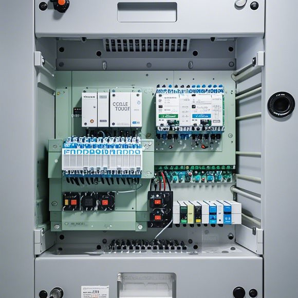
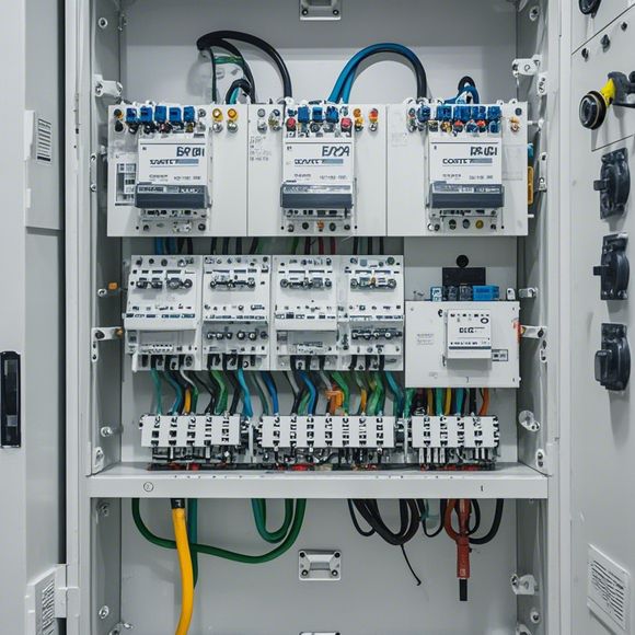
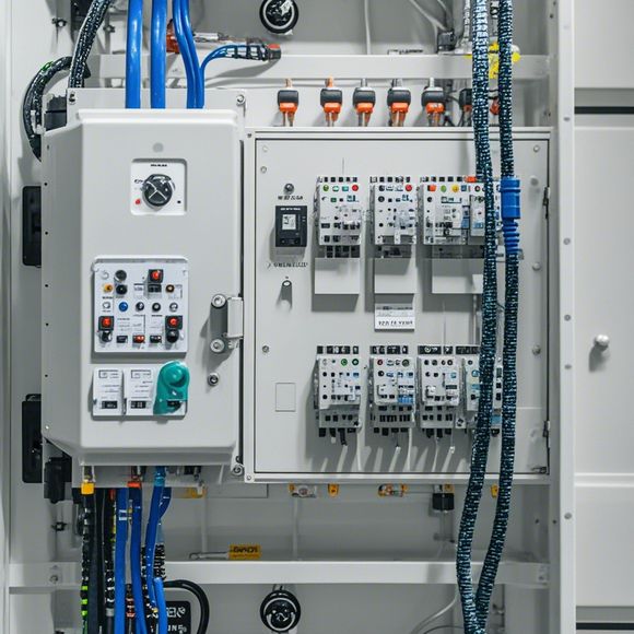
Starting at the top-left corner of the control panel, you'll see a series of connectors labeled as "A," "B," "C," etc. These are where your wires will go. Each color represents a different function or input/output (I/O) port, so make sure to match them up correctly.

For example, if your PLC has three inputs, you'll need three sets of wires labeled "IN1," "IN2," and "IN3." And if it has one output, you'll only need one set of wires labeled "OUT," which should connect to a corresponding terminal block.
Now, let's say you're working on a project that involves multiple devices, like a mixer and a sensor. You'll need to connect the sensor's input to the "IN1" port of your PLC and its output to the "OUT" port of your PLC. Then, for the mixer, you'll want to connect its input to the "IN2" port and its output to the "OUT" port of your PLC.
But wait, there's more! Some PLCs come with a special switch labeled "SEL" that you can use to program your PLC to perform different functions based on certain conditions. For instance, if you have two sensors, you might want to program your PLC to turn on the mixer when both sensors read high (a signal that means something is happening). In this case, you'd connect the sensors' inputs to the "IN1" and "IN2" ports of your PLC, and the mixer's input to the "IN1" port, with the mixer's output going to the "OUT" port.

And that's just scratching the surface! There are countless combinations you can make with your PLC wiring based on your needs and the capabilities of your particular PLC. But remember, consistency is key—make sure you label all your connections clearly so that nobody gets lost in translation later on.
So there you have it, folks! A basic guide to connecting your PLC wiring for your next trade mission. Remember, it's not just about getting it done quickly; it's about making sure it works flawlessly from the outset. Happy coding!
Content expansion reading:

Articles related to the knowledge points of this article:
Smart Manufacturing Solutions with PLC Integrated Machinery
How to Use a PLC Controller for Your Business
PLC (Programmable Logic Controller) Control System Basics
The Role of Programmable Logic Controllers (PLCs) in Foreign Trade Operations