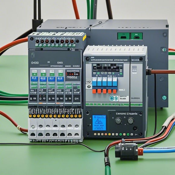
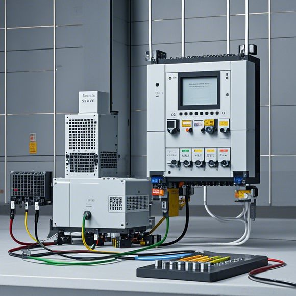
Introduction to the PID Controller Wiring Diagram for Factory Automation
In the world of factory automation and industrial control, there's a critical component that plays a crucial role in ensuring smooth operation: the PID Controller Wiring Diagram. This diagram is like an invisible hand guiding every step of the process, making sure everything runs smoothly and precisely.To understand how this wiring diagram works, let's imagine it as a complex network of wires, each carrying signals to and from various sensors and actuators. These signals are then processed by the PID controller, which adjusts the settings according to the feedback received from the system. The result? Enhanced efficiency, reduced error, and improved overall performance.But don't just take my word for it – here's what a few experts have to say about the importance of this diagram in modern factories. "The PID controller wiring diagram is the lifeblood of any factory automation system," says one expert. "It ensures that all the pieces fit together seamlessly, from sensors to actuators to the control system itself." And another adds, "Without this diagram, we risk chaos on the production line, with unpredictable results and potentially costly mistakes."So the next time you're thinking about automating your factory, remember: a solid PID controller wiring diagram is not just a piece of paper – it's a vital part of your industrial success story.
As a professional in foreign trade operations, it's crucial to understand how to connect and control factory equipment using PLC (Programmable Logic Controller). In this guide, I will provide an overview of the PID Controller wiring diagram, which is essential for ensuring efficient and accurate factory automation.

First off, let's start with the basics. The PID Controller is a type of controller that adjusts the system response based on its input and feedback. It consists of three parts: Positive Output Limiter (P), Integrator (I), and Derivative Comparator (D). These components are connected to form a closed-loop system that regulates the output signal.
Now, back to the wiring diagram. The first step is to identify the components involved in the PID control system. These include sensors, actuators, and the PLC itself. Next, we need to determine the connections between these components. This involves understanding the signals that flow through each component and how they are transmitted from one device to another.
For example, let's say we have a temperature sensor that measures the temperature of the process fluid. This sensor sends a signal to the PLC, which then compares it with a set point value. If the actual temperature deviates from the set point, the PLC generates a signal to activate an actuator, such as a heater or cooler, to adjust the temperature.

The wiring diagram should show how the different components are connected to form this feedback loop. For example, the sensor may be connected to a pin on the PLC, while the output of the PLC may be connected to an actuator via a motor controller. Additionally, there may be other connections between the PLC, actuator, and other components in the system.
In addition to the wiring diagram, it's also important to consider how power and communication are handled within the system. For example, the PLC may require a power supply to function properly, while the actuator may require communication protocols to communicate with other devices in the automation system.
Another consideration is safety features. For example, there may be emergency stop buttons or alarms installed in the factory automation system to alert operators in case of an emergency. The wiring diagram should indicate where these safety features are located and how they are connected to the other components.

In summary, understanding the PID Controller wiring diagram requires familiarity with the components involved and their connections to form a feedback loop. This information is essential for effective factory automation and can help reduce downtime and improve production efficiency.
Content expansion reading:
Articles related to the knowledge points of this article:
Smart Manufacturing Solutions with PLC Integrated Machinery
PLC Controller Selection Guide for Foreign Trade Operations
Mastering the Art of Plc Controllers: A Comprehensive Guide to Understand and Implement
PLC Controller Wiring Guideline
PLC Programming for Automation Control in the Manufacturing Industry