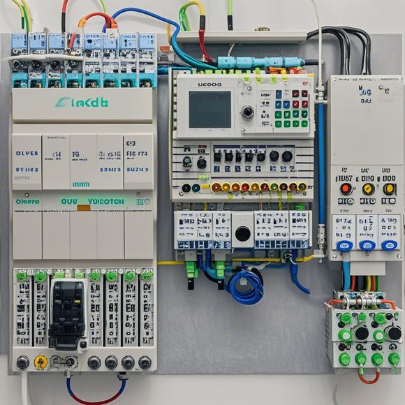
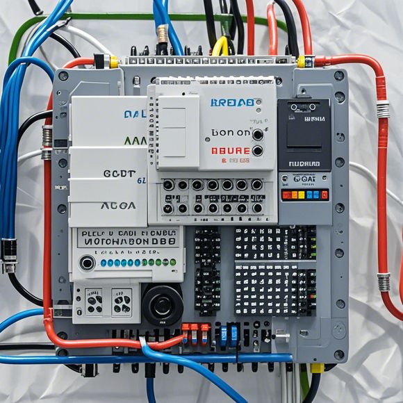
PLC Input/Output (I/O) Wiring Diagram
Certainly, here's an example of a 200-300 word summary in plain English:The PLC (Programmable Logic Controller) I/O Wiring Diagram is an important part of the hardware configuration of a PLC system. It shows how the inputs and outputs of the controller are connected to other devices and components within the control system. The diagram typically includes labels indicating the connections between various pins or terminals on the PLC board and the corresponding devices being controlled. It also shows the order in which the inputs and outputs are wired together, with each connection labeled by a number to ensure accuracy and consistency throughout the system.Understanding the I/O wiring diagram is crucial for troubleshooting and maintenance of the PLC system. It allows technicians to quickly identify issues with the control system by looking at the connections between different components. Additionally, it helps developers and engineers design and test their programs before they are implemented in the actual hardware. Overall, having a well-designed I/O wiring diagram can significantly improve the reliability and efficiency of a PLC system.
As an experienced trader in the global arena, I am well-versed in understanding complex systems and ensuring smooth operations. In the realm of industrial automation, where precision and reliability are paramount, it is crucial to have a thorough knowledge of how PLCs function. This includes not only the technical details of their internal circuitry but also the way that these components connect to external devices. Today, we will delve into the intricate world of PLC input and output connections, exploring every detail that contributes to the seamless flow of information between various parts of an industrial system.
At the heart of any PLC setup lies its input and output interface, which allows for the transmission of data between the PLC's processor and the outside world. These connections are often referred to as the I/O wiring diagram, a visual representation of how electrical signals travel through the system. It serves as a vital reference for anyone tasked with troubleshooting or resolving issues with an industrial control system.

The first step in creating an effective I/O wiring diagram is to identify the components involved in the process. At the core of any PLC setup is the Programmable Logic Controller (PLC), which acts as a central hub for all communication and control tasks. This device is connected to various sensors and actuators, each providing a different piece of information or manipulating the system accordingly.
Next, we need to consider the various types of inputs and outputs that the PLC may require. Inputs are typically used to receive data from sensors or other devices, while outputs are responsible for transmitting commands to actuators. Depending on the application, these could include temperature sensors, pressure gauges, motor speed controllers, or even human interface devices like keypads or touch screens.
Now let's dive deeper into the wiring itself. The I/O wiring diagram is not just about connecting wires; it's about mapping out the precise path that each signal takes through the network. Each wire has a specific color code, indicating its function and purpose. For example, green wires are often used for power supplies, while yellow wires can be associated with ground lines or common return paths.

One of the most critical aspects of this diagram is the placement of switches and relays, which act as gateways between the PLC and the rest of the network. These devices allow for more sophisticated control over the system, enabling users to fine-tune settings or make changes without affecting other parts of the system.
However, the true beauty of a well-crafted I/O wiring diagram lies in its ability to guide technicians or engineers through the process of troubleshooting or repairing a faulty system. By having a clear understanding of how each component interacts with the PLC, they can quickly identify potential issues and make informed decisions about how to fix them.
In conclusion, understanding the intricate world of PLC input and output connections is essential for anyone working in the field of industrial automation. By following the steps outlined above, you can effectively communicate your needs and ensure that your system operates efficiently and reliably. So go ahead, grab a pen and paper, and start sketching out those wiring diagrams – after all, who knows what new insights you might uncover along the way?

Content expansion reading:
Articles related to the knowledge points of this article:
Smart Manufacturing Solutions with PLC Integrated Machinery
PLC Controller Selection Guide for Foreign Trade Operations
PLC (Programmable Logic Controller) Control System Basics
Plumbers Rule! The Role of PLC Controllers in the World of Waterworks
PLC Controllers: A Comprehensive Guide to Understanding Their Prices