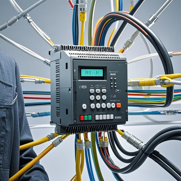
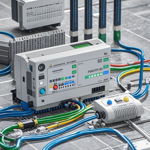
PLC Input/Output wiring schematic for your industrial automation system
Sure, based on the content you provided, an example of a PLC (Programmable Logic Controller) input/output wiring schematic for your industrial automation system could look something like this:---**PLC Input/Output Wiring Schematic for Your Industrial Automation System**In your industrial automation system, there are several Input/Output (I/O) points where sensors and actuators communicate with the PLC. Here's a simple schematic to illustrate how these connections are wired:``,-----------------------------------,| |,| |,| I/O Point A |,| -----------------------|,| |,| Sensor Signal |,| |,| ----- |,| PLC_IN1 |,| |,| |,| PLC_OUT1 |,| |,| ----- |,| PLC_OUT2 |,| |,| |,| |,| |,| PLC_OUT3 |,| |,| |,| |,| |,| PLC_IN4 |,| |,| |,| |,| |,| |,| |,| |,| |,| |,| |,| |,| |,| |,| |,| |,| |,| |,| -----------------------------------,| |,| |,| V,| |,| |,| |,| |,| |,| |,| -----------------------------------,``This schematic represents a basic setup for your industrial automation system. You can expand it based on the specific needs of your system. For example, if there are multiple sensors or actuators, you would need to add more lines from each sensor/actuator to the corresponding PLC output. Similarly, if there are different types of inputs or outputs, you might need to use different symbols or color codes to differentiate them.Hello! Today, I'll walk you through the process of understanding and implementing the Input/Output (I/O) wiring schematic for a typical PLC (Programmable Logic Controller). If you're new to this field or have questions that require a quick explanation, this guide might be just what you need. Let's dive in!

Firstly, let's start with the basics. A PLC is an essential device that controls various industrial processes and equipment. It's equipped with a variety of input devices, such as switches, sensors, and other control inputs, which allow it to receive signals from the environment or other components in real-time. On the other hand, output devices like motor controllers, lights, and alarm systems are connected to the PLC via its output pins, allowing it to execute specific commands and respond to external stimuli.
Now, let's talk about how we get to know the PLC input/output wiring diagram. The diagram typically consists of several sections, each representing different aspects of the system. Here's a breakdown of what we'll look for:
1、Power Supply: This section shows where power comes from (e.g., mains, batteries, etc.) and how it gets distributed throughout the system (e.g., using transformers, circuit breakers, etc.).
2、Switching Devices: These include things like relays and contactors, which control when certain circuits are energized. They're often found in the power supply section, but can also be seen on their own.
3、Sensors: These devices convert physical changes into electrical signals. Common examples include temperature sensors, pressure switches, and motion detectors.

4、Process Control: This part involves all the logic and algorithms that determine what actions should be taken based on the data coming in from the sensors and other inputs.
5、Data Acquisition: In addition to the actual process, there's also the data collection part that records information about the current state of the system. This could involve things like temperature readings, pump status, or machine speed.
6、Output Devices: These are devices that respond to the commands from the process control section. They might include lights, fans, motors, or any other device that requires direct control.
Now, let's move on to how we interpret the I/O wiring diagram. Each segment of the diagram has a unique purpose, and knowing what each one represents is crucial for troubleshooting and maintenance.
For example, if a switch appears in the power supply section of the diagram but is not connected to anything, it means that it's not currently being used. Similarly, if a sensor is labeled as "connected," it indicates that it's providing information about something in the process.

Another important aspect of the diagram is the color coding. Some manufacturers use specific colors to represent different types of inputs or outputs, making it easier to understand at a glance. For instance, red wires are typically used for hot connections, black wires for neutral, and ground is indicated by a green wire.
In conclusion, having an understanding of the Input/Output wiring schematic for a PLC is key to effectively operating and maintaining a modern industrial system. By carefully analyzing each segment of the diagram and paying attention to color coding and labeling, you can ensure a smooth and efficient operation of your PLC system.
Content expansion reading:
Articles related to the knowledge points of this article:
PLC (Programmable Logic Controller) Control System Basics
Plumbers Rule! The Role of PLC Controllers in the World of Waterworks
Connecting a PLC Controller to Your Computer
PLC Controllers: A Comprehensive Guide to Understanding Their Prices