PLC Control Principle Diagram
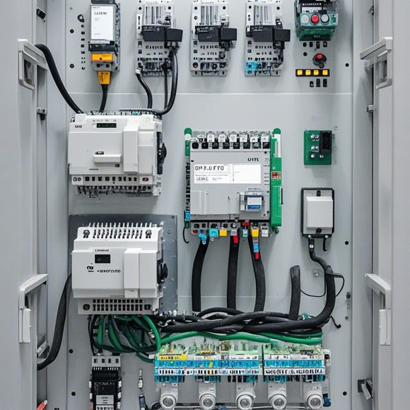
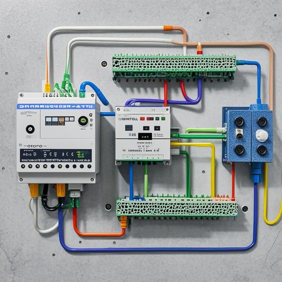
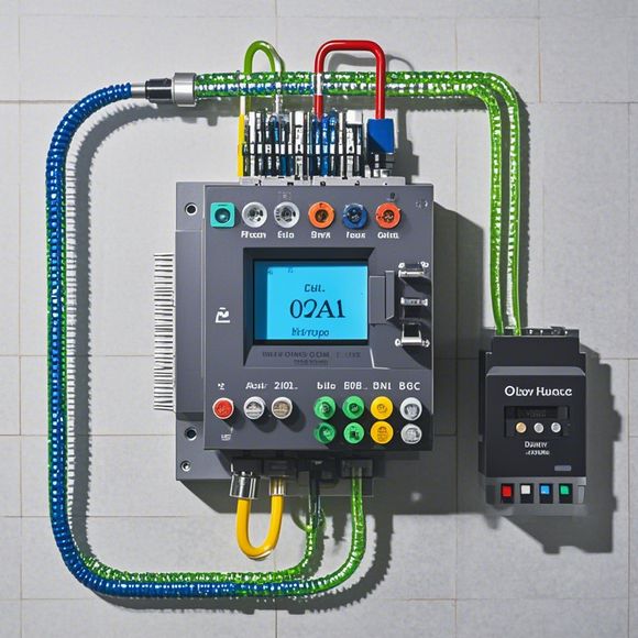
PLC (Programmable Logic Controller) 是一种用于自动化控制和工业过程控制的电子设备。它通过编程实现了对各种设备的控制,包括传感器、执行器、驱动器等。PLC的控制原理图是一张显示了这些设备及其之间连接关系的图表。在这张图中,每个节点代表一个设备,如传感器或执行器。它们通过连线相互连接。如果有一个传感器连接到一个输入端口,那么这个传感器就会把数据发送到PLC。PLC会根据接收到的数据来控制输出端口的执行器。PLC的控制原理图通常包括以下几个部分:1. 输入端口:这是从外部设备接收数据的地方。,2. 输出端口:这是将数据发送到外部设备的地方。,3. 中间处理单元:这是PLC内部的处理器,负责处理接收到的数据并根据预设的逻辑进行决策。,4. 程序存储器:这是存储PLC程序的地方。,5. 输入/输出接口:这是PLC与其他外部设备通信的接口,包括RS232/RS485串行接口和Profibus等现场总线接口。PLC控制原理图是一张展示PLC与外部设备之间连接关系和工作流程的图表。它可以帮助工程师更好地理解系统的功能和结构,从而设计和优化自动化控制系统。
Introducing the PLC (Programmable Logic Controller) control system, a powerful tool for controlling industrial processes. The PLC is a digital computer that can be programmed to perform various tasks based on instructions stored within its memory. These systems are widely used in manufacturing, automation, and other industries due to their reliability, efficiency, and flexibility.
The PLC control principle diagram is an essential document that outlines the components and connections of the system. It includes the input devices such as sensors, switches, and actuators that provide feedback on the status of the process being controlled. The output devices include motors, pumps, and valves that control the movement of the process. The PLC communicates with these devices through a network of wires and connectors, allowing it to read data from the input devices and send commands to the output devices.

To operate the PLC, users need to write or program the software using a programming language such as Ladder Logic, Function Block Diagram (FBD), or Plug-in Structured Text (PST). Once the program is written, the user can upload it to the PLC and test it for accuracy and functionality. The program can be customized to meet specific needs of the process being controlled.
One example of how the PLC control principle diagram works can be seen in a simple pneumatic system. The system consists of a pneumatic controller, air cylinders, and pressure sensors. The pneumatic controller receives input signals from the sensors and determines the desired pressure level for the air cylinders. It then sends control signals to the air cylinders to adjust their volume, which affects the flow of air into the system.
Another common application of the PLC control principle diagram is in a chemical plant. In this case, the PLC controls the operation of various equipment such as mixers, tanks, and conveyors. It monitors the concentration of chemicals in the tanks and adjusts the flow rate of the mixing liquids accordingly to ensure consistent product quality. The PLC also takes into account safety factors and prevents overfilling of tanks to avoid spills and potential hazards.

In addition to industrial applications, the PLC control principle diagram can also be found in automotive engineering. Here, the system manages engine performance by monitoring various parameters such as fuel injection and exhaust emissions. The PLC controls the throttle position and fuel injection timing to achieve optimal combustion efficiency.
Overall, the PLC control principle diagram is a vital component of today's modern industrial and automotive systems. Its ability to integrate complex systems and control them efficiently makes it a preferred choice for many industries. By understanding the principles behind the PLC control, businesses can optimize their operations and achieve greater productivity and efficiency.
Content expansion reading:

Articles related to the knowledge points of this article:
PLC (Programmable Logic Controller) Control System Basics
Plumbers Rule! The Role of PLC Controllers in the World of Waterworks
The Role of Programmable Logic Controllers (PLCs) in Foreign Trade Operations