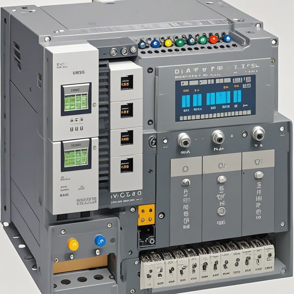
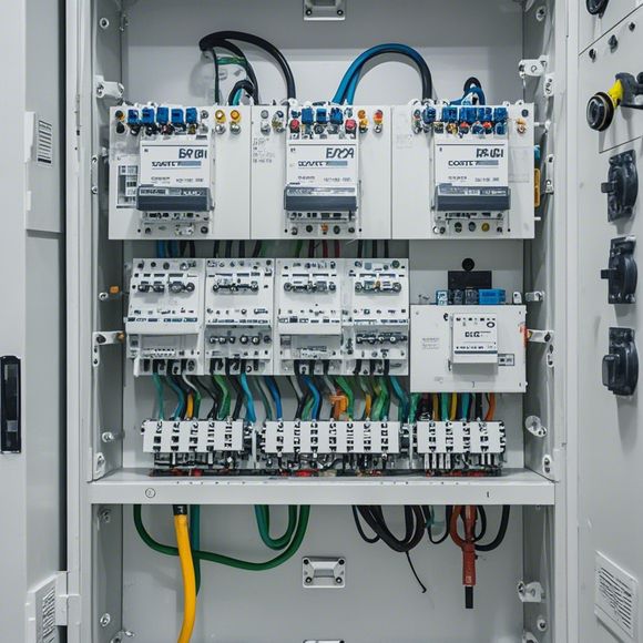
Introduction to the PLC Controller Wiring Diagram
In this introduction, we will delve into the intricate world of Programmable Logic Controllers (PLCs) and their wiring diagrams. These controllers are the backbone of industrial automation systems, responsible for coordinating and controlling various processes. The key to a successful PLC system lies in its precise wiring diagram, which serves as a blueprint for the communication between various components.A wiring diagram is essentially a visual representation of how different electrical components are interconnected within the PLC system. It includes symbols representing sensors, actuators, input devices, output devices, and other critical components. Each component is assigned a unique symbol or number, and the lines connecting them represent the electrical connections required to function properly.Understanding the wiring diagram is essential for troubleshooting and maintenance. It allows technicians to identify faulty connections, determine which components are working correctly, and optimize the performance of the PLC system. Moreover, it helps in designing new systems by providing a clear understanding of the components involved and their interrelationships.In conclusion, the wiring diagram of a PLC controller is an indispensable tool for ensuring the smooth operation of industrial automation systems. By carefully analyzing and interpreting the diagram, engineers can make informed decisions that optimize the performance of the system and prevent future problems.
Dear all, today I am excited to share with you a vital aspect of our business operations - the PLC controller wiring diagram. As we all know, the PLC (Programmable Logic Controller) is an essential piece in modern manufacturing and automation systems. It allows for precise control and monitoring over various process parameters within industrial settings. Without proper understanding of its wiring diagram, it becomes challenging to operate and troubleshoot PLCs effectively. Therefore, let's dive into the details of this critical part of our operations.
Firstly, the PLC controller wiring diagram serves as a blueprint or roadmap that guides the placement of wires and connectors within the system. It includes information about how different components are interconnected and how signals are transmitted from one device to another. This diagram is crucial because it ensures that each wire has the correct path and that the connections are secure and reliable. A poorly designed wiring diagram can lead to faulty connections, reduced efficiency, and even safety hazards.
Now, let's take a closer look at some common components found in a typical PLC controller wiring diagram. There are several main types of components, including:
1、Input Devices: These are sensors and transducers that measure physical quantities such as temperature, pressure, or flow rates. They are connected to the PLC through input ports on the wiring diagram. For example, if you have an industrial furnace, the temperature sensor will be connected to a corresponding input port on the PLC controller.

2、Output Devices: These are actuators that perform specific functions based on the signals generated by the PLC. They are also connected to the PLC through output ports on the wiring diagram. For example, if you have a conveyor belt in your production facility, the motor control signal from the PLC will activate the motor via an output port.
3、Process Control Components: These include logic gates, relays, timers, and counters that help to manage and control the overall operation of the system. The wiring diagram will show where these components are connected to other circuits and what they do in the system.
4、Power Supplies: In addition to supplying power to the PLC, the wiring diagram will also show the connections between the PLC and other electrical devices in the factory. This includes transformers, switches, and circuit breakers.

Now, let's move on to the importance of understanding and maintaining a proper PLC controller wiring diagram. Properly functioning wiring diagrams ensure that every component in the system is connected correctly and securely. If there are any issues with the wiring, it can lead to incorrect data transfer, misinterpreted signals, or even dangerous situations. Therefore, regular inspection and maintenance of the wiring diagram is critical to keep the system running smoothly and safely.
In conclusion, the PLC controller wiring diagram is a vital tool in ensuring the efficient and safe operation of any industrial system. By understanding the components and connections within the diagram, we can avoid common errors and maintain the integrity of the system. Remember, proper wiring is not just about connecting wires; it's about securing them and making sure that they work together seamlessly. Let's embrace this knowledge and continue to improve our operations and customer satisfaction with every step we take!
Content expansion reading:

Articles related to the knowledge points of this article:
PLC Controller Selection Guide for Foreign Trade Operations
Plumbers Rule! The Role of PLC Controllers in the World of Waterworks
PLC Controllers: A Comprehensive Guide to Understanding Their Prices
Effective Strategies for Handling PLC Control System Faults
PLC Controller Advantages: A Comprehensive Guide for Success in Global Trade
Mastering the Art of PLC Control: Unlocking Industry-Grade Automation Powerhouses