PLC Input and Output Interface Diagram: A Comprehensive Guide for Your Automation Project
In this guide, we will delve into the world of PLC (Programmable Logic Controller) Input and Output Interface Diagrams. These diagrams are a crucial part of any automation project as they serve as the communication link between the various hardware devices in your system.The first step in creating an Input and Output interface diagram is to understand the basic components involved. These include sensors, valves, motors, and other devices that you want to control. Each component has a specific purpose and should be connected to the correct input or output pin on the PLC according to its functionality.Once you have identified the components you need, the next step is to create the diagram itself. This can be done using various software tools available for PLC programming, such as Ladder Logic Editor, Structured Text Editor, or Graphical User Interface. The key is to ensure that each connection is clearly labeled and labeled with the appropriate pin number.Finally, it's important to test your Input and Output interface diagram thoroughly before deploying it. This includes verifying that all connections are secure and that the PLC is functioning correctly. By following these steps, you can create an effective Input and Output interface diagram that will help you achieve your automation goals.
Dear colleagues,
I hope this message finds you well. As a seasoned professional with extensive experience in the field of automation and project management, I am thrilled to share with you an essential tool that is integral to our daily work - the PLC (Programmable Logic Controller) input and output interface diagram.
The PLC, or Programmable Logic Controller, is a sophisticated piece of machinery designed to automate industrial processes and systems. Its ability to process data, execute instructions, and respond to changing conditions makes it a game-changer in the manufacturing and industrial world. In this context, having the correct knowledge about its input and output interface is crucial, as it ensures seamless communication between the PLC and various components of the system.

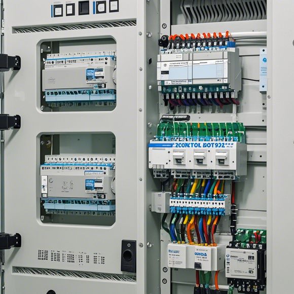
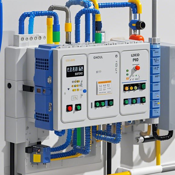
Let's delve into the details behind this intricate diagram. The first step is understanding what constitutes a PLC input/output (I/O) interface diagram. This document serves as a visual representation of how the PLC communicates with external devices such as sensors, actuators, and other components of the system. It outlines the electrical connections between various points on the PLC board and their corresponding external components. By following the diagram, one can easily identify the inputs and outputs that need to be wired up to ensure smooth operation.
Now, let's talk about the importance of a well-crafted input/output interface diagram. A good schematic not only helps us visualize the connections but also provides a reference point for future modifications or upgrades. When designing or modifying a system, changes often occur that require adjustments to the wiring. Having a clear diagram enables us to identify the exact connections needed for these changes, ensuring that we do not disrupt the flow of data or cause any functional issues.
Moreover, a well-written I/O interface diagram helps us understand the power requirements of each component connected to the PLC. Different devices have different power needs, and understanding these requirements beforehand can prevent costly overloads or power issues during operation. Additionally, it aids in troubleshooting by identifying which parts are functioning correctly and which ones require further examination.

In terms of design considerations, when creating an input/output interface diagram, it is essential to consider factors such as voltage, current, and frequency ranges of the devices being connected to the PLC. Proper labelling and annotation of all components is crucial for easy comprehension and maintenance. It is also important to note that the diagram may vary depending on the manufacturer and the specific application requirements, so it is advisable to consult the relevant documentation for accurate information.
In conclusion, a well-designed input/output interface diagram is not just a technical document; it is a bridge between your automation system and its surrounding environment. It provides a roadmap for success, ensuring that every device in the system operates efficiently and reliably. So, if you're looking to streamline your operations, enhance efficiency and reliability, then investing time in creating a detailed and accurate I/O interface diagram is undoubtedly worth it. Let's embrace this responsibility together and create a world of automation where every device shines like a diamond. Thank you for considering my insights today.
Content expansion reading:

Articles related to the knowledge points of this article:
Mastering the Art of Plc Controllers: A Comprehensive Guide to Understand and Implement
The cost of a PLC Controller: A Comprehensive Analysis
PLC Programming for Automation Control in the Manufacturing Industry
Connecting a PLC Controller to Your Computer
PLC Controllers: A Comprehensive Guide to Understanding Their Prices