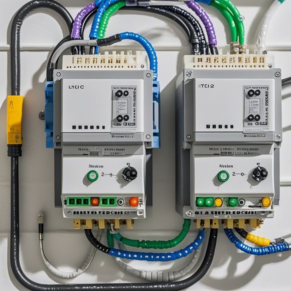
Introduction to PID Controller Wiring Diagrams in English
PID controller wiring diagrams are essential tools for understanding and implementing proportional-integral-derivative (PID) control systems in English. These diagrams show the connections between various components of a PID controller, including inputs, outputs, and sensors, as well as the flow of signals through the system.To generate an effective summary, start by introducing the concept of PID control systems and their role in modern engineering applications. Then, describe the basic elements of a PID controller, such as the proportional (P), integral (I), and derivative (D) components. Next, explain how the wiring diagram organizes these components, showing the relationships between them and illustrating the flow of information throughout the system.Finally, emphasize the importance of understanding PID controller wiring diagrams in English to effectively design, analyze, and troubleshoot PID control systems in a variety of industrial and scientific contexts.
As an experienced exporter, you're likely dealing with various electronic devices that require precise control. One such piece of technology is a Programmable Logic Controller (PLC) controller, which plays a crucial role in industrial automation and manufacturing processes. A PLC controller's wiring diagram is the blueprint for connecting various components to perform their functions effectively.

To ensure optimal performance, understanding how these wiring diagrams are constructed is essential. Let me break down the process for you, starting with understanding the basic components of a typical PLC controller.
1、Input Devices:
- These are sensors or switches that detect physical conditions or signals. For example, proximity sensors might detect objects near the door, triggering a safety system.
2、Output Devices:
- Actuators like motors, valves, or lights respond to inputs from the controller. For instance, when a button on a machine tool is pushed, the motor will turn on or the light will illuminate.
3、Process Control:
- This is where the controller takes input from the sensors and determines the appropriate action based on preset logic rules. For example, a temperature sensor could set off a heating system if it detects an overheating condition.
4、Communication:
- The PLC controller communicates with other devices in the factory network using protocols like PROFIBUS or Ethernet. This allows for data exchange between different systems and ensures seamless integration.
Now, onto the actual wiring diagram itself. Here's what you need to know about each component:
Input Devices:
- They are connected to the PLC via dedicated pins. You'll notice that some have multiple pins; this is because they can detect multiple signals simultaneously.
- When connecting sensors or switches, make sure to label each pin correctly. This not only helps with troubleshooting but also ensures compatibility with other devices.

Output Devices:
- These devices are directly connected to the PLC's output ports. Some output modules can handle multiple actuators at once, making them ideal for large factories.
- It's important to check the maximum current rating of the output device before powering it up. This prevents overloading and potential damage.
Process Control:
- Here, you'll find the program code that controls the flow of information within the PLC. This includes algorithms for temperature control, motion tracking, and other critical functions.
- To ensure accuracy, regularly update the program code with new requirements or changes in the factory environment.
Communication:
- The wiring diagram will show the connections between the PLC and other devices in the factory network, such as HMI screens or other automation systems.
- Ensure that each connection is secure and properly labeled for future maintenance purposes.
In conclusion, understanding the intricacies of a PLC controller's wiring diagram is crucial for effective automation. By following these tips and practices, you can ensure that your equipment operates efficiently and reliably, leading to increased productivity and profitability in your business.
Content expansion reading:
Articles related to the knowledge points of this article:
Smart Manufacturing Solutions with PLC Integrated Machinery
The cost of a PLC Controller: A Comprehensive Analysis
PLC Programming for Automation Control in the Manufacturing Industry
How to Use a PLC Controller for Your Business
Plumbers Rule! The Role of PLC Controllers in the World of Waterworks