Understanding the Plug and Play (PLC) Control Cabinet wiring diagram
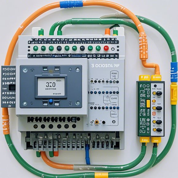
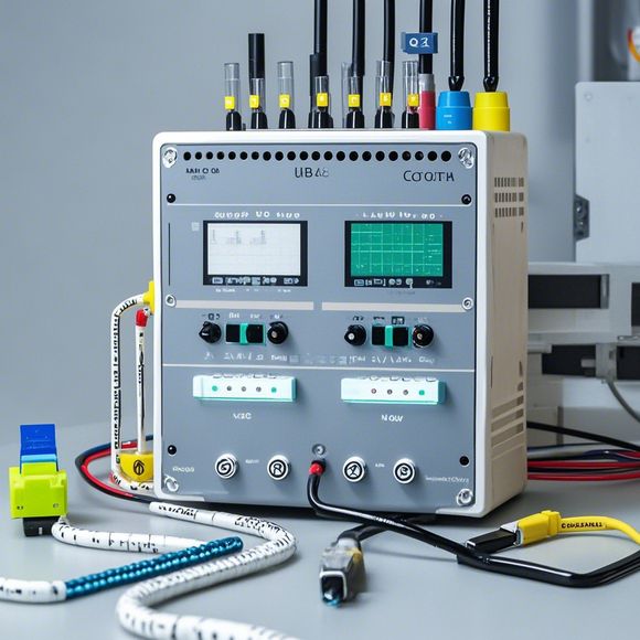
The Plug and Play (PLC) Control Cabinet is a device that allows for easy integration of various electronic components into a computer system without the need for extensive setup. This means that you can plug in different devices, such as sensors, motors, or actuators, and configure them directly through the PLC control panel.To properly wire the PLC cabinet, you'll want to ensure that all connections are made correctly and securely. This usually involves using wires with appropriate voltage ratings, making sure that all connections are grounded correctly, and following any specific wiring diagrams provided by the manufacturer.Once everything is connected, you'll need to test the PLC to ensure that it functions correctly and that all devices are communicating properly. This may involve running tests on individual components or performing more comprehensive tests to verify that the entire system is functioning as intended.
In today's digital world, automation is becoming increasingly important in various industries for efficiency and cost reduction. A plug-and-play control cabinet is one of the most versatile solutions that can be integrated into a wide range of applications. To ensure seamless operation, it's crucial to understand how the control cabinet's electrical wiring diagram functions, from the basic principles of power supply and signal transmission to advanced features like programmable logic controllers (PLCs).
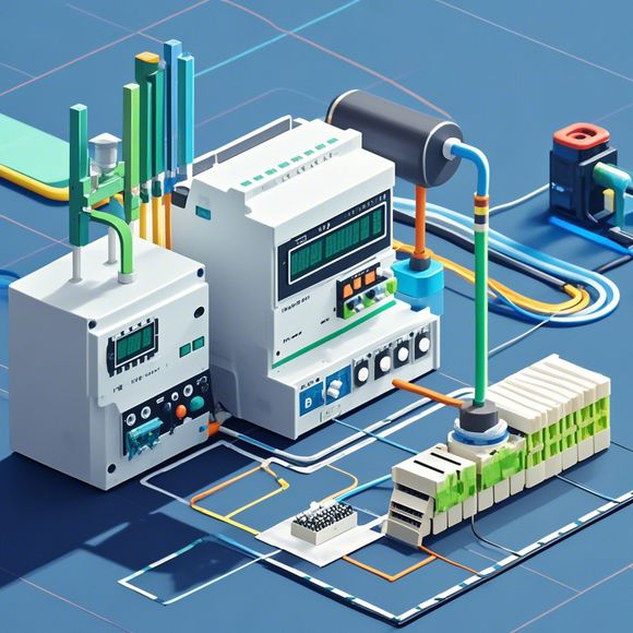
Firstly, let's talk about the basics. A plug-and-play control cabinet consists of various components such as switches, relays, sensors, and actuators that are controlled by a centralized processing unit, which is typically an PLC. The wiring diagram serves as a blueprint that outlines the connections between these components, allowing for precise programming of actions.
For example, consider a heating system where you need to regulate the temperature based on environmental conditions. The plug-and-play control cabinet will have sensors that detect changes in temperature, while the PLC will be responsible for processing this data and making decisions based on predefined algorithms. This could involve adjusting the heating elements to maintain a specific set point or triggering a fan to cool down during peak demand periods.
The wiring diagram would show how different inputs (sensor signals) are connected to the PLC, which then controls output devices (heaters or fans), which in turn affect the environment around the control cabinet. This interconnection ensures that the system operates as intended without manual intervention.

Now, let's delve deeper into the complexities of PLC control cabinets. One of the key features of a plug-and-play control cabinet is its flexibility. With PLCs, you can implement sophisticated algorithms and decision-making capabilities, allowing for customized solutions tailored to specific needs. For instance, you might use a PLC with built-in memory and processing capabilities to store historical data and make predictions about future performance, thereby optimizing energy consumption and reducing costs.
Another essential aspect of plug-and-play control cabinets is their modular design. Instead of having one centralized control unit, modern systems often consist of multiple modules that can be easily replaced or upgraded. This allows for scalability and maintenance, enabling you to adapt to changing requirements over time.
Moreover, communication protocols play a critical role in ensuring smooth operation. Modern PLCs use standardized protocols such as PROFIBUS or DeviceNet, which facilitate seamless integration with other devices and systems. By understanding these protocols, you can ensure that your control cabinet works harmoniously with other hardware components, enhancing overall performance.

One common challenge when working with plug-and-play control cabinets is ensuring compatibility across different manufacturers. However, with proper documentation and testing, you can overcome this issue and ensure that your system runs smoothly across different platforms.
In conclusion, understanding the electrical wiring diagram of a plug-and-play control cabinet is crucial for any automation professional. It not only helps you troubleshoot issues but also provides insights into how the system can be optimized for optimal performance and cost-effectiveness. By following the principles outlined above, you can confidently navigate the world of automated control systems, ensuring reliable and efficient operations.
Content expansion reading:

Articles related to the knowledge points of this article:
Smart Manufacturing Solutions with PLC Integrated Machinery
PLC Controller Selection Guide for Foreign Trade Operations
The cost of a PLC Controller: A Comprehensive Analysis
PLC Programming for Automation Control in the Manufacturing Industry
Connecting a PLC Controller to Your Computer
PLC Controllers: A Comprehensive Guide to Understanding Their Prices