PLc Control Cabinet Wiring Diagram Master Guide
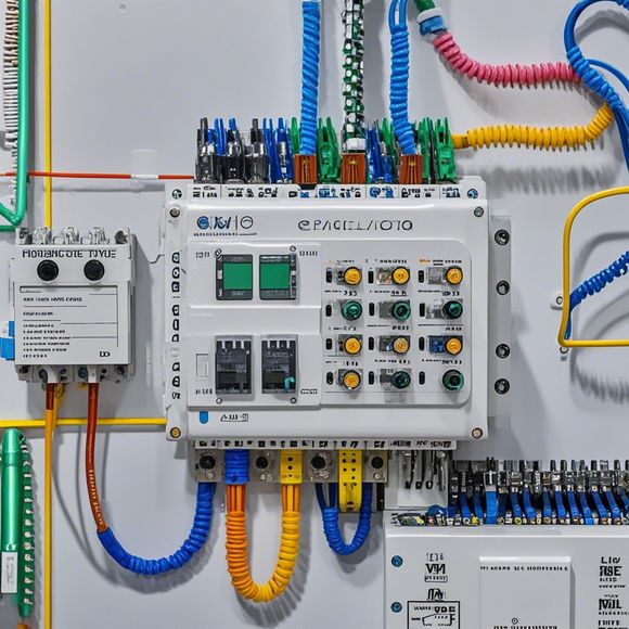
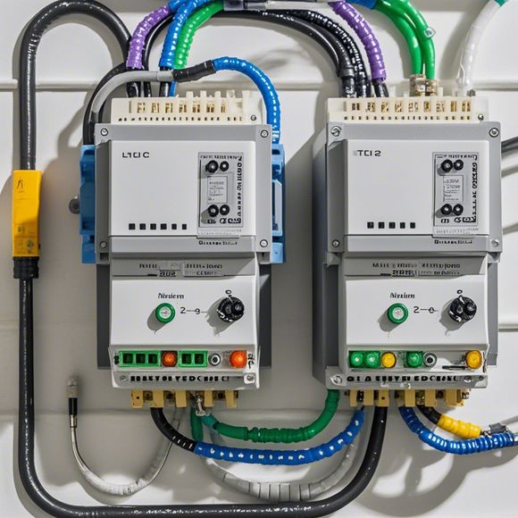
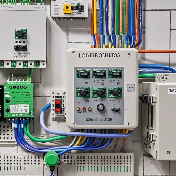
In this guide, we will walk through the wiring diagram for the PLC (Programmable Logic Controller) Control Cabinet. This is a crucial component in any industrial or manufacturing environment, as it allows for precise control and management of complex processes.Firstly, let's understand what an PLC is. An PLC stands for Programmable Logic Controller, which is a device that can be programmed to perform a variety of tasks based on instructions from a computer or other device. It is widely used in industries such as automotive, chemical, and manufacturing.Now, let's look at the main components of an PLC Control Cabinet. These include the CPU (Central Processing Unit), which is the brain of the system; the memory, which stores the programming code and data; and the input/output modules, which allow for communication with external devices.The wiring diagram for the PLC Control Cabinet will typically show the connections between all these components. This diagram should clearly indicate where each wire goes, and how it is connected to the various components in the cabinet.Overall, understanding the wiring diagram for an PLC Control Cabinet is critical for maintaining and troubleshooting the system. With this guide, you should have a good understanding of the different components and their functions, as well as how they are connected together.
Introduction:
Welcome to the world of industrial automation, where precision and reliability are paramount. In this digital age, we rely on electronic devices to manage our systems, and one such critical component is the Programmable Logic Controller (PLC). But with so many wires and connections, it can be overwhelming for a beginner or an inexperienced technician to understand and connect them correctly. That's where we come in - our comprehensive guide to PLC control cabinet wiring diagrams. This master guide aims to simplify the process of connecting wires and assembling your PLC system, ensuring that everything is connected securely and effectively. Whether you're a seasoned engineer or just starting out, this guide has got your back. So, let's dive into the details and learn how to navigate the world of PLC wiring like a true expert!
Understanding the Basics

Before diving into the specifics of wiring diagrams, it's essential to have a basic understanding of what a PLC is. A Programmable Logic Controller, commonly referred to as a PLC, is a digital computer that controls various types of machinery, including industrial equipment, robotics, and automation systems. It allows for precise and efficient operations by processing input signals and generating output commands. The PLC is designed to work with sensors, actuators, motors, and other hardware components, allowing for complex logic and algorithms to be implemented within its programming software.
Now that we have a clearer picture of what a PLC is, it's time to delve deeper into the world of wiring diagrams. These diagrams are essential for any electrical project involving the use of the PLC. They provide a visual representation of the electrical connections between various components, including sensors, switches, relays, motors, and PLC itself. By studying these diagrams, we can quickly identify the correct wiring points and avoid common mistakes that could lead to costly repairs or even safety hazards.
The Importance of Wiring Diagrams
Wiring diagrams play a crucial role in any industrial automation project. They serve as the foundation for ensuring that all wires are connected securely and efficiently. Properly labeled and detailed diagrams help us to understand the circuitry involved and identify any potential issues before they become problems. Additionally, wiring diagrams provide us with a reference point for troubleshooting and maintenance, making it easier to diagnose and resolve any electrical issues that may arise during the course of the project.
Identifying the Need for a Guide
Given the complexity of wiring PLC systems, it's no surprise that there is a growing demand for guidance and tutorials. Many individuals and companies find themselves struggling to connect wires and assembling their PLC systems, leading to frustration and potential delays in projects. This is where our guide comes in - we aim to provide a comprehensive overview of PLC control cabinet wiring diagrams, making them accessible to anyone looking to learn more about this fascinating technology.
Exploring the Detailed Content

Our guide covers every aspect of PLC control cabinet wiring diagrams, from the basic concepts to advanced techniques. Here's a breakdown of what you can expect to discover in this comprehensive guide:
1、Introduction to PLC Control Cabinets: This section provides an overview of what a PLC control cabinet is and its purpose in modern industrial applications. You'll learn about the different types of PLCs available and the benefits they offer in terms of flexibility, efficiency, and cost-effectiveness.
2、Wire Diagram Symbols: Every PLC wiring diagram is made up of symbols, which are used to represent different parts of the system. We break down the most commonly used symbols, providing definitions and examples of each one.
3、Basic Components: From sensors to motors, each component plays a crucial role in the operation of a PLC system. We discuss the functions of each component and provide tips for identifying them in the wiring diagrams.
4、Connectivity Points: Once we have identified the components, it's important to know where to connect them together. We explain the different types of connections and the tools required to make them.
5、Advanced Techniques: As our knowledge grows, so does our ability to connect PLC systems more efficiently. We cover advanced techniques such as using jumpers instead of soldering wires, using multimeters for testing connections, and implementing safety features like grounding.
6、Troubleshooting Tips: Even the best wiring diagrams can sometimes lead to misinterpretations, resulting in incorrect connections or unintended outcomes. We provide troubleshooting tips and strategies to ensure that your project stays on track.

7、Case Studies: To illustrate the practical application of our guide content, we include case studies of successful PLC installations. These case studies will help you see the impact of proper wiring practices and demonstrate the value of investing time in learning about this technology.
8、Conclusion: In this section, we summarize the key points covered in the guide and encourage readers to take actionable steps towards improving their own PLC wiring skills. We also highlight some resources available for further learning and development.
Closing Thoughts
In conclusion, learning how to connect wires in a PLC control cabinet is an essential skill for anyone involved in industrial automation. With our comprehensive guide, you'll be equipped with everything necessary to tackle any wiring project with confidence. Remember, practice makes perfect – so don't hesitate to apply what you've learned through case studies and troubleshooting tips. Good luck on your next project!
Content expansion reading:
Articles related to the knowledge points of this article:
PLC Programming for Automation Control in the Manufacturing Industry
PLC (Programmable Logic Controller) Control System Basics
The Role of Programmable Logic Controllers (PLCs) in Foreign Trade Operations
Connecting a PLC Controller to Your Computer
PLC Controllers: A Comprehensive Guide to Understanding Their Prices