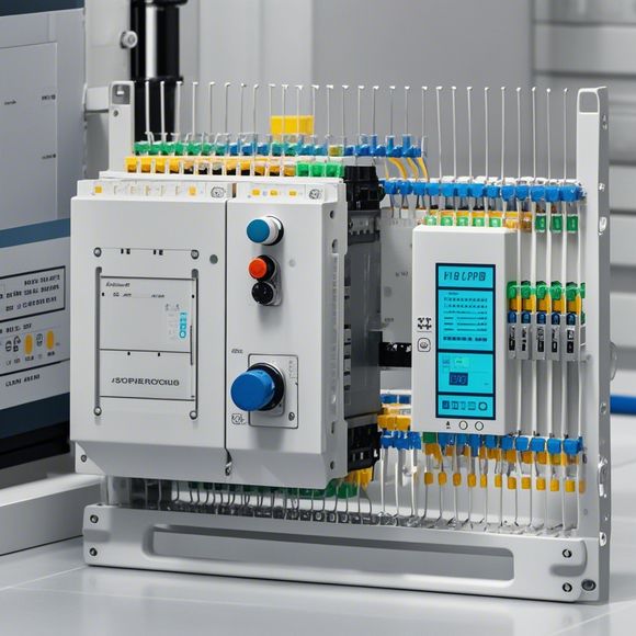
PLC Controller Wiring Diagram for Your Next Import and Export Project
Introducing the PLC Controller Wiring Diagram for your upcoming import and export projects. As a leading provider of industrial automation solutions, we understand the importance of precise wiring in ensuring the smooth operation of your manufacturing processes.To assist you in achieving this, we have designed a comprehensive PLC controller wiring diagram that takes into account the specific requirements of your business. Our diagram will provide you with detailed information on how to wire up the various components of your PLC system, including sensors, actuators, and input/output modules.We believe that this wiring diagram will help you streamline your manufacturing processes, reduce downtime, and increase overall efficiency. With our expertise, you can be confident that your PLC controller wiring is secure and reliable, enabling you to focus on what really matters: running your business successfully.
Introduction:

Hello, everyone! As a seasoned trader with a keen eye for detail, I'm thrilled to be here today to guide you through the intricacies of your next import and export project using a popular piece of machinery - our PLC controller. With this comprehensive wiring diagram in hand, we can confidently navigate through the complexities and ensure a smooth operation of this critical piece of equipment.
Step 1: Gathering Information
Before diving into any technical aspect, it's essential to gather all the necessary information about your PLC controller. This includes identifying its model number, operating voltages, and input/output (I/O) pin configurations. These details will serve as the foundation for our wiring diagram.
Step 2: Understanding the Controller
Once you have the basic information, take some time to familiarize yourself with the PLC controller's capabilities. This includes understanding its programming languages, communication protocols, and data processing functions. By doing so, you'll be well-equipped to troubleshoot any potential issues that may arise during the installation process.
Step 3: Creating the Wiring Diagram
Now that we have a clear understanding of the PLC controller, we can begin creating the wiring diagram. Start by laying out the main connections between the controller and various components such as sensors, actuators, and other control devices. Use diagram symbols like wires, switches, and connectors to clearly indicate each component's location and function.
Step 4: Detailing the Connections
With the wiring diagram laid out, it's now time to dive deep into the details of each connection. For example, how do you connect the sensor's signal output to the PLC's input port? How are the motor's power inputs connected to the controller? Each step should be detailed, including the color coding and specification of each wire.
Step 5: Highlighting Special Considerations

As we delve deeper into the wiring diagram, it becomes apparent that there are certain aspects worth highlighting. For instance, if your controller requires special protection against electromagnetic interference, make sure to include a shielded cable connection. Or, if your system requires high-speed communication, opt for a dedicated network cable instead of an Ethernet cable.
Step 6: Testing the Connectivity
Once we've completed all the wiring, it's important to test the connectivity thoroughly. This involves verifying that each component is working correctly and that all connections are secure and reliable. Use a multimeter or other testing tools to ensure that the signals are transmitting and receiving properly.
Step 7: Review and Documentation
After completing the wiring, don't forget to review your work and document it accordingly. Include a description of your wiring choices, any special considerations you made for the project, and any challenges encountered during the process. This documentation can be useful for future projects, helping to avoid similar mistakes or complications.
Conclusion:
In conclusion, creating an accurate PLC controller wiring diagram is an essential step in any import and export project. By following these seven steps and paying close attention to detail, you can ensure that your machine operates smoothly and efficiently. Don't hesitate to reach out to us if you have any questions or need further assistance throughout the process.
Content expansion reading:
Articles related to the knowledge points of this article:
Smart Manufacturing Solutions with PLC Integrated Machinery
Connecting a PLC Controller to Your Computer
PLC Controllers: A Comprehensive Guide to Understanding Their Prices
Effective Strategies for Handling PLC Control System Faults
What is a Programmable Logic Controller (PLC)
Mastering the Art of PLC Control: Unlocking Industry-Grade Automation Powerhouses