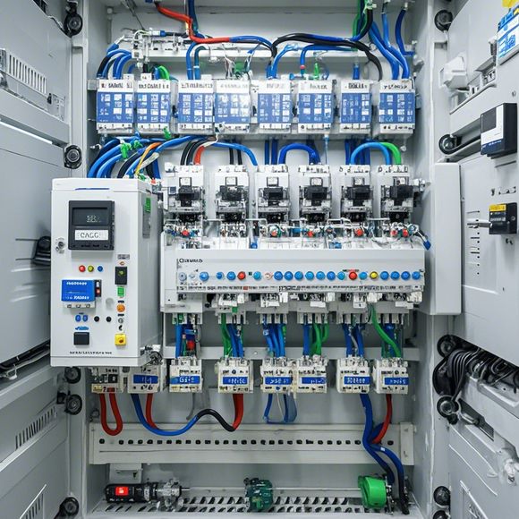
PLC Module wiring diagram
The PLC (Programmable Logic Controller) module wiring diagram is a visual representation of the electrical connections between various components in an automation system. It typically includes diagrams of the input and output modules, as well as their respective connections to the controller board. The wiring diagram also shows how these components are interconnected, including relays, motors, and other electronic devices that make up the control system.In a typical PLC module wiring diagram, you can see wires labeled with numbers or letters indicating which component they connect to. These labels provide a quick reference to identify where power and data signals are coming from or going to different components within the system. Additionally, the diagram often includes schematic symbols for common electronic components like transistors, resistors, and capacitors.Overall, the PLC module wiring diagram is crucial for understanding how the hardware components in an industrial or manufacturing environment interact to perform their functions. It serves as a blueprint for troubleshooting and maintenance, ensuring that the system operates efficiently and safely.
Dear all,
As a seasoned trader in the world of electronics, I am delighted to introduce you to the intricate world of Programmable Logic Controllers (PLCs). These marvels of modern technology have revolutionized the way we control our manufacturing and industrial processes. Today, we will delve into the fascinating world of PLC module wiring diagrams, exploring the key components that make up a complete PLC system.
At its core, a PLC is a powerful tool for controlling complex machinery and processes with precision and efficiency. The key to its success lies in the wiring diagrams that guide us through the various components that make it work. Let's take a closer look at what each component does and how they come together to create a fully functional PLC system.

Firstly, the Central Processing Unit (CPU), which sits at the heart of the system, is responsible for interpreting commands from external sources and making decisions based on data inputted by the sensors. This powerful processor handles everything from basic mathematical calculations to complex algorithms, ensuring that your production lines run smoothly and efficiently.
Next, we have the Input/Output modules, or I/O modules, which are responsible for receiving and sending data between the PLC and the outside world. These modules allow you to connect various devices, such as switches, sensors, and actuators, directly to your PLC. They enable you to monitor and control critical processes, ensuring that they operate within safe and reliable limits.
The Communication modules play a crucial role in ensuring that the PLC communicates effectively with other systems in your factory or plant. These modules include things like Ethernet, Wi-Fi, Bluetooth, or other protocols that allow the PLC to send and receive information wirelessly or over long distances. By connecting your PLC to the internet, you can access real-time data on your production processes, streamline operations, and improve efficiency across the board.
Finally, let's not forget about the Safety modules, which are designed to ensure your PLC systems are safe to operate. They monitor for any potential hazards, such as overheating or short circuits, and automatically shut down the system if necessary. This prevents accidents and minimizes the risk of injury or damage to your equipment.
In addition to these essential components, there are also specialized modules available for specific industries or applications. For example, temperature control systems might require a special module that can detect and adjust temperature levels, while motion control systems might rely on advanced motion sensors and motor drives.

Now, back to our main topic - the PLC module wiring diagram. This document serves as a visual representation of how the various components come together to form a functional PLC system. It includes detailed schematic diagrams, electrical schematics, and step-by-step instructions on how to connect each component to the rest of the system.
By studying this wiring diagram, you can gain a comprehensive understanding of how your PLC works and identify any potential issues or challenges that may arise during installation or operation. This knowledge will help you troubleshoot problems quickly and efficiently, ensuring that your manufacturing processes run at optimal levels of accuracy and reliability.
In conclusion, the PLC module wiring diagram is an essential tool for anyone looking to build or maintain a successful PLC system. With its detailed breakdown of each component and clear steps for assembly, this document provides a roadmap for building a robust and efficient production control system. So, grab your pencil and paper and let's dive deeper into the world of PLC module wiring diagrams together!
Content expansion reading:
Articles related to the knowledge points of this article:
PLC Programming for Automation Control in the Manufacturing Industry
Plumbers Rule! The Role of PLC Controllers in the World of Waterworks
The Role of Programmable Logic Controllers (PLCs) in Foreign Trade Operations
Connecting a PLC Controller to Your Computer
PLC Controllers: A Comprehensive Guide to Understanding Their Prices