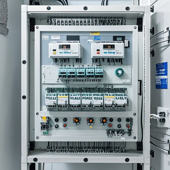
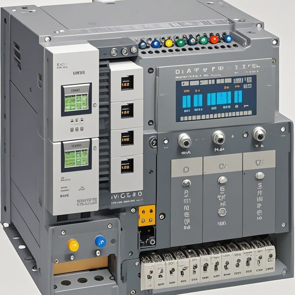
Understanding the PLC Control Cabinet Wiring Diagram
Sure, I can help you create an English summary based on the content you provided. Here's a draft:The PLC Control Cabinet Wiring Diagram is a visual tool used for understanding and designing electrical circuitry in a Programmable Logic Controller (PLC). It provides a detailed diagram of the connections between various components, such as sensors, actuators, and control panels. This diagram helps engineers quickly identify potential issues and troubleshoot problems.It includes labels and arrows to indicate the direction of current flow and the purpose of each wire connection. The diagram also shows the power source, input/output ports, and other critical components.By examining the wiring diagram, engineers can determine if the PLC can handle the required signals without compromising its functionality or safety. They can also make adjustments to the design to optimize performance and reduce costs. Overall, the PLC Control Cabinet Wiring Diagram is essential for ensuring reliable and efficient operation of the PLC system.
Hello everyone, today we are going to talk about a crucial part of our business - understanding the PLC (Programmable Logic Controller) control cabinet wiring diagram. This is a critical tool that allows us to connect all the electronic devices and components within the control cabinet to perform the required functions. So let's dive right into it!

Firstly, when we receive the PLC control cabinet wiring diagram, we should carefully read through it to understand what each component does. The diagram usually starts with the main components such as the power supply, sensors, actuators, and communication modules. Each component has a specific purpose and is connected to another component using a series of wires. For example, the power supply is connected to the sensor module, which in turn powers the actuator module. This process continues throughout the entire circuitry.
Now, let's take a closer look at how each component works together. The sensor module detects changes in the environment or physical conditions, such as temperature, pressure, or motion, and sends this information to the actuator module. The actuator module then uses this information to make a response, such as turning on or off a valve, adjusting a speed controller, or triggering an alarm system.
To ensure that everything is working correctly, it is important to check the connections between components and verify that there are no loose wires or damaged connections. If there are any issues, we need to address them immediately so that the control cabinet can function properly.
In addition to checking connections, we also need to test the functionality of each component separately before integrating them into the overall system. This helps us identify any potential problems early on, allowing us to make necessary adjustments before the entire system is put into operation.

Now, back to our topic. Let's go over some common wiring practices used in PLC control cabinets. For instance, we often use color-coded wires to distinguish between different types of signals, such as power, ground, or signal lines. This helps us identify where each wire goes and avoids confusion during installation.
Another important practice is to follow the manufacturer's specifications for wiring. This ensures that all connections are made securely and meet the required electrical standards. We also need to pay attention to the size of wires and their length, as this can affect the performance of the circuitry.
When installing the control cabinet, it is important to consider factors such as heat management, vibration levels, and environmental conditions. For example, if the location is prone to high temperatures or heavy vibrations, we may need to install additional cooling systems or dampening materials to prevent damage to the electronic components.
Finally, it is important to regularly inspect and maintain the PLC control cabinet and its wiring. This helps ensure that the system remains reliable and performs optimally. Regular maintenance also includes replacing worn-out components or cleaning up any debris that may have accumulated over time.

In conclusion, understanding the PLC control cabinet wiring diagram is crucial for ensuring that our business operations run smoothly. By following proper procedures and maintaining the system regularly, we can minimize downtime and improve productivity. So remember to always stay informed and proactive when it comes to handling PLC controls. Thank you for your attention, and I hope this brief explanation helped you grasp the basic principles behind PLC control cabinet wiring.
Content expansion reading:
Articles related to the knowledge points of this article:
Smart Manufacturing Solutions with PLC Integrated Machinery
PLC Controller for Manufacturing Automation
PLC Programming for Automation Control in the Manufacturing Industry
How to Use a PLC Controller for Your Business
PLC Controllers: A Comprehensive Guide to Understanding Their Prices