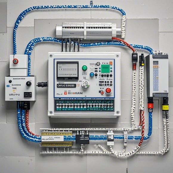
plc输入输出对照表
**The PlC Input-Output Comparison Table**In the realm of industrial control systems, the Plain Language Control Element (PLC) plays a vital role as it interfaces between the human operator's commands and the actual machinery operation. The table below provides a clear guide to understanding how inputs and outputs are connected within various types of PLCs. Firstly, let's start with the input devices. Buttons, switches, proximity sensors, photoelectric encoders, and other sensors are common components used for PLC inputs. These devices convert physical signals into electrical ones that can be read by the PLC system. For example, button inputs are typically connected to a single COM terminal on the PLC, while group inputs can be connected in various combinations depending on the requirements of the application.Moving on to output devices, relays, contactors, and solenoid valves are commonly seen as PLC outputs. These devices transform electrical signals into mechanical actions, such as opening or closing a circuit or controlling the flow of fluids. In terms of connections, each output device has its dedicated address in the PLC, making it easy to program and manage.It is also important to note that the Modbus protocol, which is widely used in industrial automation, can be easily integrated with different brands of PLC. This allows for seamless communication between PLCs and other devices, such as DCS systems.In conclusion, a detailed understanding of the input-output correspondence table is crucial for any PLC engineer or technician. By following this table, it becomes easier to connect the right input devices to the corresponding output devices and ensure that the PLC operates safely and efficiently.
"PLC Input and Output Correspondence Table: A Comprehensive Guide for Your Next Automation Project"

Content:
Hello everyone,
I'm excited to share with you the importance of having a clear understanding of our PLC's input and output characteristics. In today's world, automation has become an integral part of almost every industrial process, from manufacturing to healthcare. And when it comes to implementing these systems, having a reliable and efficient knowledge base can make all the difference. So, let's dive into the details.
First off, what exactly is a PLC? It stands for Programmable Logic Controller, a device that allows for precise control over complex industrial processes by executing a series of instructions stored in its memory. These instructions are called programs, which can be created by any programmer familiar with the language used by the PLC.
Now, back to our main topic - the PLC Input and Output Configuration. This table serves as a roadmap to ensure that your automation system operates efficiently and effectively. Here’s how it works:
Step 1: Identifying Input Devices
When designing your automation system, you need to determine which sensors or actuators will be connected to your PLC. The PLC will then send signals to these devices based on data collected by sensors or measured by actuators. For example, if you have a temperature sensor that needs to be connected to your PLC, it should be marked as a "temperature-sensitive" input device. Similarly, if you want to control a motor using a position sensor, it should be labeled as such.
Step 2: Determining Output Devices

Once you have identified your input devices, you must determine how they will be controlled by the PLC. This step involves selecting appropriate output devices based on the type of signal you want to send to each one. For instance, if your goal is to turn on a light, you would select an "output-to-light" device from the table. Similarly, if you want to move a motor, you would choose an "output-to-motor" device.
Step 3: Configuring PLC Inputs and Outputs
After identifying your input and output devices, you can now configure them on your PLC. This involves entering information about each device into the programmable logic controller's memory. You will need to specify whether each input device is a digital or analog signal, as well as any other relevant information such as voltage levels or specific ranges. For output devices, you'll need to decide on the type of signal you want to send out (e.g., 0V to activate a relay, 5V to turn on a fan) and any other necessary specifications. Once you've entered this information into the program, you can test your automation system to ensure that it functions as expected.
In conclusion, having a thorough understanding of your PLC’s input and output configuration will not only help you troubleshoot issues but also enable you to design more efficient and effective automation systems. Remember, investing time in learning how to properly configure these devices can save you both money and time down the line, so don't hesitate to seek out resources that can help you master this crucial skill.
So there you have it—the basics of how to use a PLC input and output correspondence table. If you have any questions or concerns, don't hesitate to reach out and let me know. I'm always here to assist you!
Content expansion reading:
Articles related to the knowledge points of this article:
How to Use a PLC Controller for Your Business
Plumbers Rule! The Role of PLC Controllers in the World of Waterworks
The Role of Programmable Logic Controllers (PLCs) in Foreign Trade Operations
Connecting a PLC Controller to Your Computer
PLC Controllers: A Comprehensive Guide to Understanding Their Prices