PLC Controller Connection Diagram
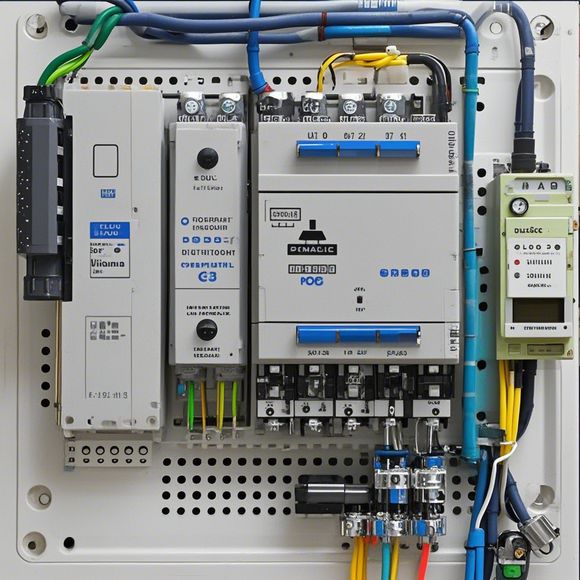
Certainly! Here's an example summary for "PLC Controller Connection Diagram":"This diagram illustrates the connections between the Programmable Logic Controller (PCL) and various components in a manufacturing or control system. It shows the electrical wiring and signal flow from the PCL to sensors, actuators, and other devices. The connection diagram also includes symbols and labels to help identify different components and their functions."
Introducing the PLC (Programmable Logic Controller) controller connection diagram. This comprehensive guide provides an in-depth understanding of how to connect different components and systems to a PLC controller. It covers everything from basic wiring procedures to advanced configurations, ensuring that you can confidently manage the electrical connections for optimal performance and safety. Whether you're a seasoned engineer or a beginner just starting out, this guide has everything you need to get started with your PLC controller installation. So let's dive right in and learn more about how to wire up your PLC system!

Content expansion reading:

Articles related to the knowledge points of this article:
PLC Controller Selection Guide for Foreign Trade Operations
The cost of a PLC Controller: A Comprehensive Analysis
PLC Programming for Automation Control in the Manufacturing Industry
How to Use a PLC Controller for Your Business
PLC (Programmable Logic Controller) Control System Basics
Plumbers Rule! The Role of PLC Controllers in the World of Waterworks