PLC Controller Wiring Diagram
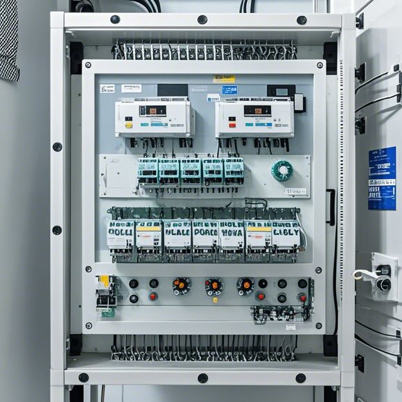
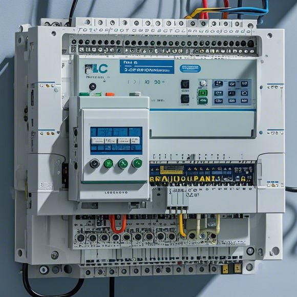
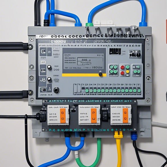
Sure, I can help you with that. Here's a 200-300 word summary of the PLC (Programmable Logic Controller) Controller Wiring Diagram:The PLC Controller Wiring Diagram is a visual representation of how the wires in a PlC are connected to the various devices and inputs/outputs within the control system. It helps to ensure that all the necessary components are properly wired and that the connections are correct, which can prevent errors during programming and operation. The diagram typically includes information such as the names of the devices, their types, and the connections between them. Additionally, it may show the voltage levels and current ratings for the wiring, as well as any safety features or protective circuitry.Overall, understanding the PLC Controller Wiring Diagram is important for anyone involved in maintaining or troubleshooting the control system, as it provides a clear picture of the electrical connections and their functions.
As a forward-thinking and innovative trade operator, you're always on the lookout for ways to streamline your operations while staying at the forefront of industry trends. When it comes to implementing PLC (Programmable Logic Controller) controllers, understanding the intricacies of their wiring diagram is key to ensuring seamless communication between various system components. This guide aims to provide a comprehensive overview of the essential elements that make up a typical PLC controller wiring diagram, along with practical tips for navigating its complexities.

At its core, a PLC controller wiring diagram serves as a visual representation of the electrical connections required to power and control various industrial devices. It consists of several key components, each with its own specific role in ensuring smooth operation. Here's what you need to know to master the art of wiring:
1、Power Supply: The first step in creating a PLC controller wiring diagram involves identifying the power sources needed to operate the PLC and associated devices. This may include direct current (DC) or alternating current (AC) power supplies, depending on the specific application. It's important to ensure that the correct voltage and current are provided to the PLC and any peripheral devices connected to it.
2、Input/Output Interface: A PLC controller wiring diagram must also include detailed information about the input/output interfaces used to connect various sensors, actuators, and other devices to the PLC. This includes pin assignments, signal types, and potential error codes or flags that indicate issues with the connections.
3、Network Topology: For larger systems with multiple PLCs or subsystems, it's essential to plan out the network topology. This involves considering how data will flow between different parts of the system, including the use of dedicated lines, crossovers, and hubs to ensure efficient communication.

4、Safety Measures: In addition to ensuring that the wiring is secure and free from short circuits or overloads, it's critical to incorporate safety features like fuses, circuit breakers, and emergency backup systems. This helps to protect against power surges, overheating, and other potential hazards.
5、Testing & Verification: After completing the wiring diagram, it's crucial to conduct thorough testing and verification to ensure that all connections are working correctly. This may involve using specialized tools like multimeters and oscilloscopes to check voltages, currents, and timing signals.
6、Documentation: Finally, keeping detailed documentation of the wiring diagram is essential for maintaining compliance with regulatory requirements and for future troubleshooting and maintenance. This includes clearly labeling each component, providing schematic diagrams, and maintaining a logbook detailing changes made to the system over time.
In today's fast-paced business environment, having a deep understanding of PLC controller wiring diagrams can be a game-changer for trade operators looking to streamline operations, reduce downtime, and improve overall efficiency. By following these tips and taking advantage of the latest technologies, you can transform the way you approach your PLC installation projects, ultimately leading to greater success in your trade operations.

Content expansion reading:
Articles related to the knowledge points of this article:
The cost of a PLC Controller: A Comprehensive Analysis
PLC (Programmable Logic Controller) Control System Basics
Plumbers Rule! The Role of PLC Controllers in the World of Waterworks
The Role of Programmable Logic Controllers (PLCs) in Foreign Trade Operations
Connecting a PLC Controller to Your Computer
PLC Controllers: A Comprehensive Guide to Understanding Their Prices