PLC Controller Wiring Diagram
Sure, here is a simplified summary of the content you provided in English:"The PLC (Programmable Logic Controller) is an electronic device used to control and automate industrial processes. It consists of a central processing unit that executes instructions from various sensors and actuators. The wiring diagram for a typical PLC controller shows how these components are interconnected and how signals flow through them. This diagram helps in troubleshooting and maintaining the system's functionality."
Dear all,
I'm excited to present our latest project - the PLC controller wiring diagram. This is a crucial part of any manufacturing or automation system, as it ensures that all the components work harmoniously together.
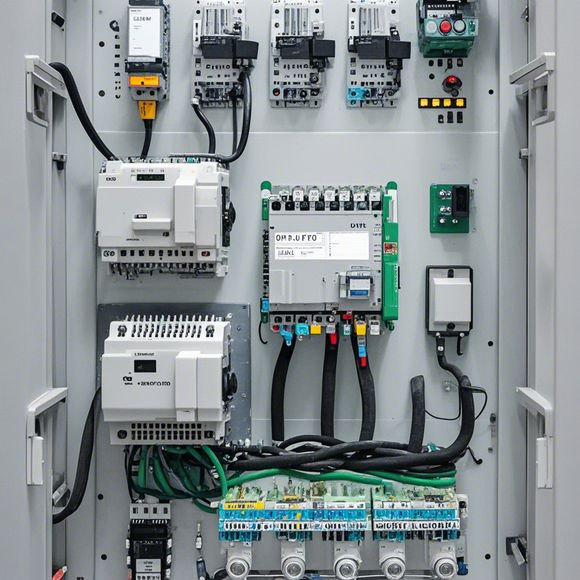
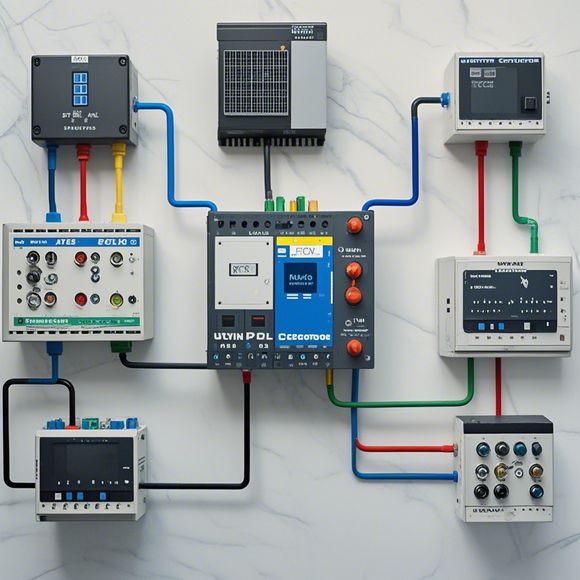
Firstly, let's start with the basics. A PLC controller is a powerful device that can control and monitor industrial processes. It consists of various inputs and outputs, which are connected to various devices such as sensors, motors, and other electronic systems. The wiring diagram is a visual representation of these connections, showing where each component is connected to another.

Now, let's break down the wiring diagram into its components. First, there is the main panel, which contains all the switches and buttons used to control the PLC system. Next, we have the input panels, which contain sensors that send data to the PLC system. These sensors are connected to various channels on the PLC, allowing for precise measurement and control of the process.
Moving on, there is the output panel, which contains relays and other devices that respond to the PLC signals. These devices are responsible for controlling the motors, lights, and other devices in the factory. Finally, there is the interlocking panel, which ensures that the PLC system cannot be compromised by any unauthorized access to the control panel.
The wiring diagram also includes labels and symbols that indicate the purpose of each component. For example, there are labels such as "Input", "Output", "Interlock", "Motor Control", and "Light Control." These labels help us identify the different functions of each component and understand their roles in the overall system.
Now, onto the importance of a good wiring diagram. Without it, we would have no way of knowing where each component is connected to the others. This could lead to confusion and errors in operation, potentially causing significant damage to the machinery or production process. With a well-designed wiring diagram, we can ensure that everything is properly connected and working together seamlessly.

In conclusion, the PLC controller wiring diagram is not just a technical document; it is a vital tool for ensuring safe and efficient operation of industrial equipment. By following this diagram carefully, we can avoid common mistakes and improve our ability to troubleshoot any issues that may arise in the future. So let's take a look at this diagram and learn how it works!
Content expansion reading:
Articles related to the knowledge points of this article:
Smart Manufacturing Solutions with PLC Integrated Machinery
Mastering the Art of Plc Controllers: A Comprehensive Guide to Understand and Implement
PLC Controller for Manufacturing Automation
Plumbers Rule! The Role of PLC Controllers in the World of Waterworks
Connecting a PLC Controller to Your Computer
PLC Controllers: A Comprehensive Guide to Understanding Their Prices