PLC Controller Principle Diagram
A PLC (Programmable Logic Controller) is a device that can be programmed to control various processes. The principle diagram of an PLC controller usually consists of input devices, output devices, and a microcontroller or central processing unit (CPU).The input devices detect the state of a process and send this information to the CPU. The CPU then interprets the data and decides what action to take based on its programming. This decision is communicated to the output devices, which control the actuators in the system.For example, if the temperature sensor detects that it's too hot, the CPU will send a command to turn off the heating system, thereby reducing the temperature. Similarly, if the pressure sensor indicates an increase in pressure, the CPU will activate a valve to release excess gas.Overall, the PLC controller is designed to provide efficient and reliable automation for various industrial processes.
As a foreign trade operations professional, understanding the principles of the Programmable Logic Controller (PLC) is crucial for effectively managing and controlling industrial processes. The PLC controller is a key component in many manufacturing and automation systems, enabling complex tasks such as monitoring, control, and data acquisition.
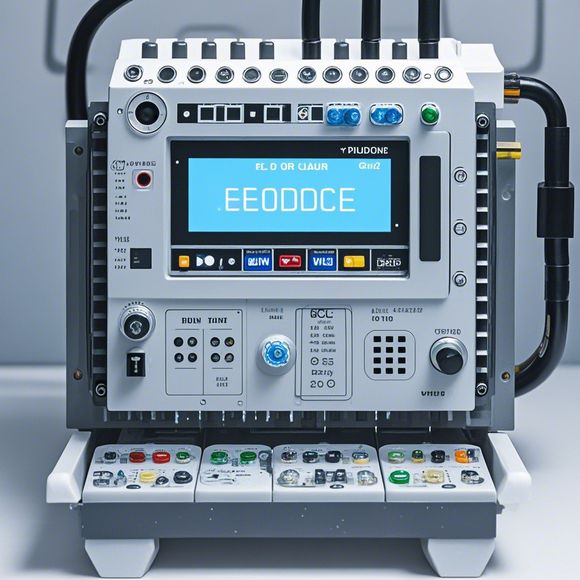
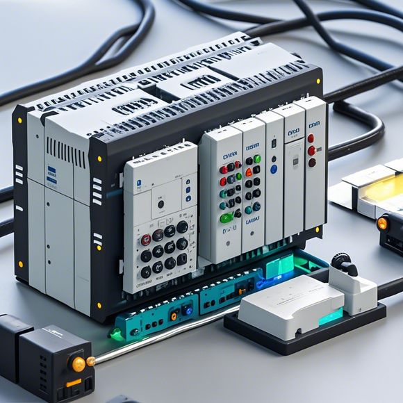
The PLC controller principle diagram is a visual representation of the components that make up a typical PLC system. It includes the input and output devices, processors, memory, and communication networks. Here's an overview of what each part does:
1、Input Devices: These are sensors or transducers that detect physical parameters such as temperature, pressure, or motion. They provide feedback to the PLC, which can then make decisions on how to control the process based on the detected information.
2、Output Devices: These are motors or actuators that convert electrical signals into mechanical motion to control the process. For example, when the PLC receives a command to turn on a fan, the output device sends a signal to the fan, which starts operating.

3、Process Control System (PCS): This is the core component of the PLC, responsible for interpreting the commands from the PLC and executing them. The PCS typically includes a microprocessor, which performs real-time calculations based on the input data and generates appropriate output commands.
4、Data Acquisition and Control System (DACCS): This is a separate system that collects data from various sources and provides it to the PLC. For instance, if there's a sensor reading an object's position, this data would be sent to the DACCS, which would store it for later analysis.
5、Networking: PLC systems are often connected through a network, allowing multiple PLCs to communicate with each other and share data. This enables more complex automation systems to be implemented, such as those involving multiple machines or factories.
6、Programming: The programming language used to create the PLC program defines the instructions that will be executed by the PLC. This could be anything from simple logic statements to complex algorithms.

7、Software Development Kit (SDK): The SDK provides developers with tools and libraries they can use to develop applications and interfaces with the PLC. This makes it easier to integrate new features or modify existing ones over time.
8、Communication Protocols: Different PLC systems may use different communication protocols, such as PROFIBUS or Ethernet. Knowing these protocols allows for smooth communication between different systems and devices within the same network.
9、Safety Features: Many modern PLC systems include built-in safety features, such as emergency stop buttons or fault detection circuits. These help prevent accidents caused by unexpected events.
10、Modular Design: Some PLC systems are designed in a modular way, allowing for easy upgrades or replacement of individual components without affecting the rest of the system.

In summary, the PLC controller principle diagram is a vital tool for any engineer or operator looking to understand the inner workings of a PLC system. By studying this diagram, one can gain a better understanding of how to troubleshoot and maintain PLCs in various industries, ensuring reliable and efficient operation of production processes.
Content expansion reading:
Articles related to the knowledge points of this article:
PLC Controller Wiring Guideline
How to Use a PLC Controller for Your Business
PLC (Programmable Logic Controller) Control System Basics
Plumbers Rule! The Role of PLC Controllers in the World of Waterworks