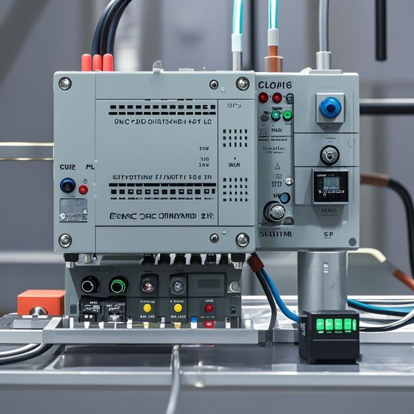
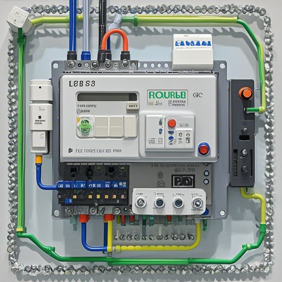
Introduction to the PID Controller Wiring Diagram for a Successful Automation Project
The introduction to the pid controller wiring diagram is a crucial step in the automation project. It helps in setting up the control system and connecting all the components together. The diagram provides a visual representation of how different components, such as sensors, actuators, and processors, are wired together. This ensures that the control system works seamlessly and accurately, allowing for efficient monitoring and adjustment of the process variables. By following the instructions in the diagram, we can ensure that the PID controller is properly installed and connected to the appropriate sensors and actuators. This will ultimately lead to a successful automation project that meets our specific needs and requirements.
Dear colleagues,
Welcome to this tutorial on the essential components of a PID controller wiring diagram. As you delve into the world of automated systems and industrial control, understanding the basics of PID (Proportional-Integral-Derivative) controllers is crucial for ensuring your projects are both reliable and efficient. In this guide, we will cover everything from reading an actual wiring diagram to implementing it in practice.

So, let's start by breaking down what we need to know about PID controllers and their importance in modern automation systems. A PID controller is a type of feedback loop used in control systems to maintain a steady state output. This controller consists of three main parts: Proportional (P), Integral (I), and Derivative (D). Each part has a distinct role in the overall system's behavior.
The Proportional (P) component measures the error between the current state and the set point. If the error is too high, the controller increases the output signal, causing a decrease in the error. Conversely, if the error is too low, the controller reduces the output signal, which causes an increase in the error.
The Integral (I) component accounts for past errors by adding them up and adjusting the output signal based on that accumulation. This helps smooth out oscillations and provides a more consistent response compared to a simple proportional controller.
Finally, the Derivative (D) component measures the rate of change of the error signal. It helps to prevent overshooting and ensures that the controller stays within its desired range.

Now, let's move on to the practical aspect of wiring. First, identify the various components of your PID controller, including the sensors, actuators, and other devices that you will interface with the controller. Once you have identified these, you can begin to map out the wires that connect them to the PID controller.
One important thing to keep in mind is that you should always use appropriate power supplies and ground connections for your components. Additionally, make sure that all wires are securely connected and not exposed or damaged. This not only protects your equipment but also ensures that the controller operates properly.
As you work through the wiring process, it is important to follow the instructions provided by the manufacturer or engineer who designed your system. They will have specific guidelines for connecting different components and ensuring proper functioning of the entire system.
In summary, understanding the PID controller wiring diagram is critical to successful implementation of automation projects. By following the steps outlined above and taking care to connect each component correctly, you can ensure that your system operates at optimal performance levels. So grab your tools and get ready for a rewarding journey towards smarter and more efficient manufacturing!

Content expansion reading:
Articles related to the knowledge points of this article:
How to Use a PLC Controller for Your Business
PLC (Programmable Logic Controller) Control System Basics
Connecting a PLC Controller to Your Computer
PLC Controllers: A Comprehensive Guide to Understanding Their Prices