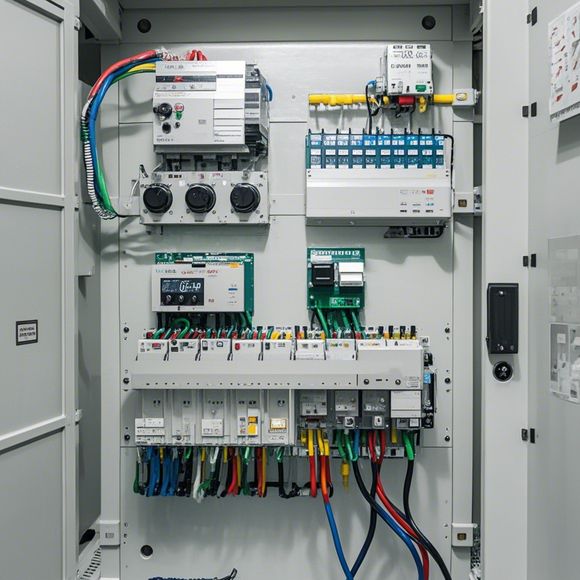
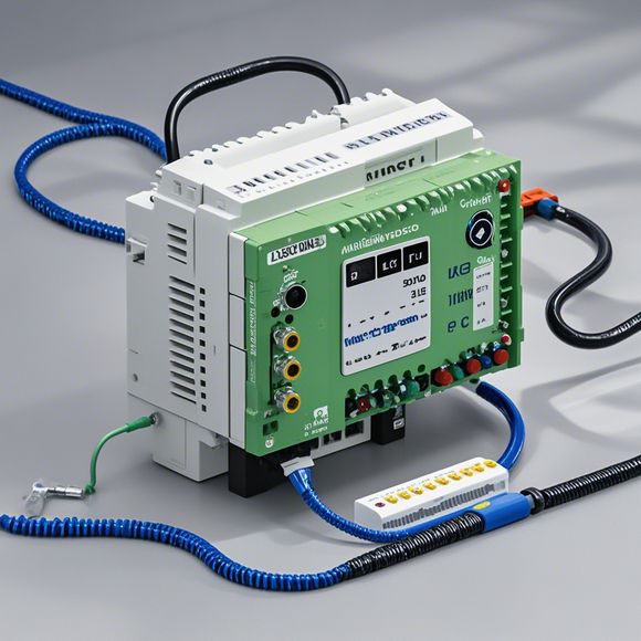
PLC Control Principle Diagram
Sure, here's a summary in English for your PLC (Programmable Logic Controller) Control Principle Diagram:The PLC Control Principle Diagram is a visual representation that illustrates the logic and flow of information within a programmable controller. It shows how different components are connected to each other and how they interact to control various functions of a system. The diagram typically includes icons representing sensors, actuators, input/output ports, and other relevant elements. It also shows the connections between these elements and the commands that are sent to them.The key components of this diagram include the CPU (Central Processing Unit), which executes the program code stored on the PLC. The memory, which stores the PLC's software and data. The input/output ports, which allow the PLC to communicate with various devices and sensors in the system. The output modules, which send signals to the actuators that control physical systems such as motors or valves. And the communication modules, which enable the PLC to connect to other devices and systems through wireless networks or serial lines.Overall, the PLC Control Principle Diagram provides an essential tool for understanding how PLCs work and how they can be used to control complex industrial processes.
In the realm of modern industrial automation, the PLC (Programmable Logic Controller) plays a crucial role as the brain behind many of today's complex manufacturing systems. At its essence, an PLC is a powerful device that can execute a series of instructions stored on its internal memory to control various functions in a factory environment.

When it comes to designing and implementing a PLC system, there are several key elements that must be considered in order to ensure optimal performance and efficiency. These include selecting the appropriate type of PLC for the specific application, programming the PLC with relevant software, and configuring the physical wiring within the factory to connect the PLC to the various devices and sensors required for effective operation.
One critical aspect of the PLC control system is the design of the logic flowchart, also known as the program code. This code determines how each function will be executed by the PLC and how different components interact with one another. It involves creating a sequence of events that defines when each step of the process should occur, as well as specifying the inputs and outputs required for successful operation.
To develop the program code for a PLC, one must first understand the fundamental principles of digital logic circuits, including binary operations such as AND, OR, NOT, and XOR. These operations are used to create more complex functions that enable the PLC to perform tasks such as counting up or down, monitoring temperature levels, controlling valves, and more.
Once the logic flowchart has been designed, the next step is to write the actual program code for the PLC. This involves translating the logical steps into a set of instructions that the PLC hardware can follow. The programming language used for this task varies depending on the specific brand and model of PLC being used. Common options include ladder diagrams, structured text, and high-level languages like Assembly and C.

Within the programming code, there are numerous variables and parameters that must be defined in order to establish communication between the PLC and other components within the factory. This includes defining the range of input values, specifying which sensors and actuators need to be connected, and determining how often data needs to be updated or processed.
The final step in developing a PLC program involves testing and debugging the code to ensure it works properly and efficiently within the production environment. This involves running simulations or test scenarios to identify any potential issues or errors before they become operational problems. By following these steps carefully and paying attention to detail, manufacturers can create reliable and efficient PLC systems that drive their factories to success.
Content expansion reading:
Articles related to the knowledge points of this article:
PLC Controller Selection Guide for Foreign Trade Operations
Mastering the Art of Plc Controllers: A Comprehensive Guide to Understand and Implement
The cost of a PLC Controller: A Comprehensive Analysis
PLC (Programmable Logic Controller) Control System Basics
The Role of Programmable Logic Controllers (PLCs) in Foreign Trade Operations