PLC Module Wiring Diagram
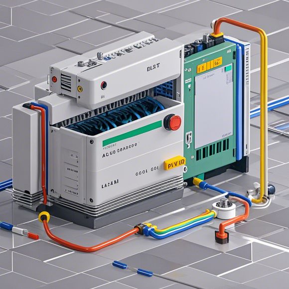
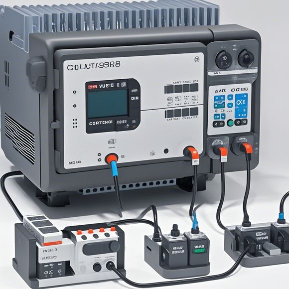
Certainly, here's a summary based on the content you provided, which seems to refer to a PLC module wiring diagram.---**Summary:**In this PLC (Programmable Logic Controller) module wiring diagram, we can see the various components that make up an industrial control system. The main components are the CPU (Central Processing Unit), which is the brain of the controller; the I/O modules, responsible for receiving and sending signals; and the power supply, which ensures the controller runs without interruptions or malfunctions. The wiring diagram shows how these components are connected, indicating the correct sequence and placement to ensure proper functioning. Each line and connection represents a specific signal or function between the different elements, helping to understand how the system communicates and operates in real-world applications.
Introduction and Overview of PLC Module Wiring Diagram:
In the realm of modern industrial automation, PLC (Programmable Logic Controller) systems play a crucial role in automating complex processes. These systems are designed to control various industrial processes, from simple machinery to large-scale factories. To ensure that these systems function efficiently, it is essential to understand the basic components and how they interact. One such component is the PLC module, which is responsible for processing and controlling the signals received from various sensors and actuators.

The purpose of this wiring diagram is to provide an overview of how the PLC module is connected to other components in the system. It will help us to understand the electrical connections between the PLC module, the input/output interfaces, and the other components of the system. This knowledge is essential when troubleshooting or modifying the system to ensure that it functions properly.
Components Connected to the PLC Module:
1、Power Supply: The power supply provides the necessary voltage and current for the PLC module to function. It is essential to connect the PLC module to the power supply correctly, as failure to do so can cause the module to shut down or produce erratic outputs.
2、Input/Output Interfaces: These interfaces connect the PLC module to other devices in the system. They receive signals from sensors or actuators, process them, and transmit the results to the PLC module. In some cases, multiple input/output interfaces may be used to connect different devices to the same PLC module.
3、Actuators: Actuators are devices that produce motion or change in state based on inputs from the PLC module. Examples include motors, switches, and valves. They are connected to the PLC module through the input/output interfaces to perform their tasks.
4、Sensors: Sensors are devices that detect physical or chemical changes in the environment and send corresponding signals to the PLC module. Examples include temperature sensors, pressure sensors, and motion sensors. These sensors are connected to the PLC module through the input/output interfaces to monitor and control the system's performance.
5、Other Hardware Devices: Depending on the specific application, there may be other hardware devices connected to the PLC module. These could include alarm systems, security systems, and other critical systems that require precise timing and coordination with the PLC module.

Wiring Diagram Analysis:
Once we have identified the components connected to the PLC module, we must analyze the wiring diagram to identify any redundant connections or potential issues that may arise. For example, if two input/output interfaces are connected to the same PLC module, it may result in incorrect readings or conflicting signals being sent to the PLC module. Similarly, if a faulty connection is made between two components, it can cause the PLC module to malfunction or produce erratic outputs.
To address these potential issues, we should carefully inspect each component and verify that it is properly connected to the PLC module according to the wiring diagram. This involves checking for loose connections, damaged wires, and any signs of wear and tear on the components. If any issues are found, we should address them promptly to prevent further damage or operational issues in the system.
Conclusion and Next Steps:
In conclusion, understanding the wiring diagram for a PLC module is crucial for maintaining and troubleshooting industrial automation systems. By following the steps outlined above and analyzing the components connected to the PLC module, we can identify potential issues and take corrective actions to ensure that the system operates smoothly and efficiently. Remember, investing in regular maintenance and inspection of your industrial automation system is key to avoiding costly downtime and ensuring optimal performance.
Content expansion reading:
Articles related to the knowledge points of this article:
PLC Controller Selection Guide for Foreign Trade Operations
PLC Programming for Automation Control in the Manufacturing Industry
How to Use a PLC Controller for Your Business
The Role of Programmable Logic Controllers (PLCs) in Foreign Trade Operations
PLC Controllers: A Comprehensive Guide to Understanding Their Prices