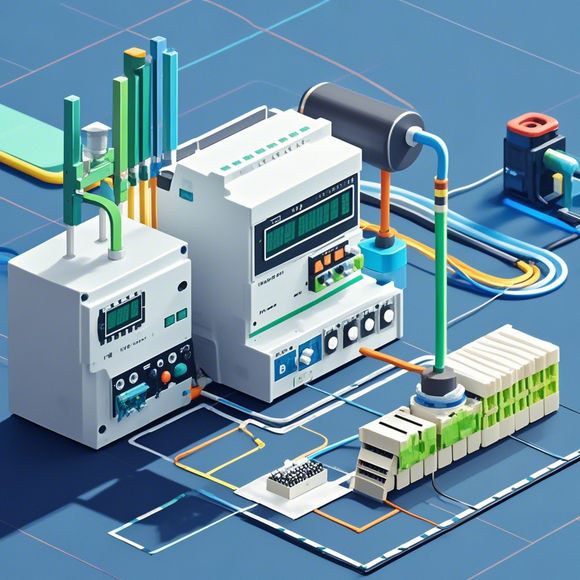
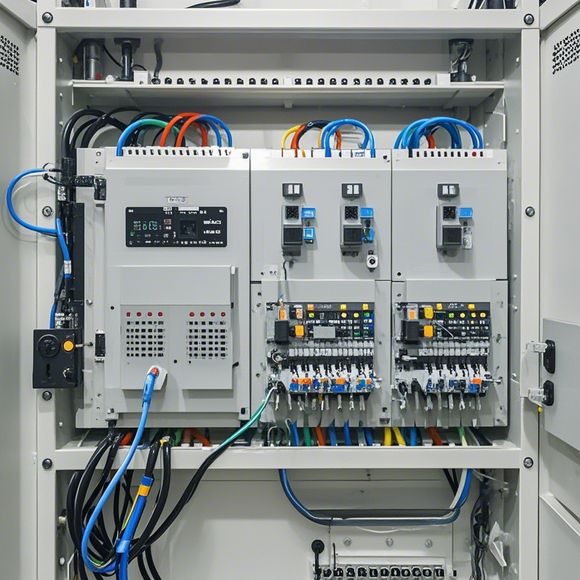
Introduction to PID Controller Wiring Diagram
Sure! Here's a brief summary of the PID controller wiring diagram:,The PID controller, which stands for Proportional-Integral-Derivative, is a type of control system used in various applications. It consists of three main parts: proportional (P), integral (I), and derivative (D) elements, which work together to adjust the output signal based on the error between the set point and the current output value.In the wiring diagram, you will find the inputs, outputs, and connections between components. The inputs are typically labeled as the set point, error, and time constants. The output is usually the control signal that regulates the process. The connections between components indicate how the different parts of the controller interact with each other.Overall, understanding the PID controller wiring diagram is important for debugging and troubleshooting industrial processes. By following the correct wiring schematics, engineers can ensure that their systems are functioning properly and efficiently.
In the realm of industrial automation, PLCs (Programmable Logic Controllers) play a crucial role in controlling and coordinating various industrial processes. A PID controller, which stands for Proportional-Integral-Derivative controller, is one of the most commonly used types of PLC that regulates process parameters by adjusting inputs according to their proportional, integral, and derivative values. This guide will provide an overview of the PID controller's wiring diagram, highlighting the key components and how they interact to create a robust control system.
To begin with, let's break down the PID controller into its basic components. The first step is the input signal, which is typically provided by sensors or other measurement devices that detect changes in process variables. These signals are then fed into the PLC's Processing Unit (CPU). The second component is the PID algorithm, which calculates the output value based on the input signal and compares it with setpoints. Finally, there's the output signal, which is sent to the actuators that drive the process equipment.
Now let's dive deeper into the wiring diagram. The PLC's CPU is connected to the input signals via a series of digital I/O ports, where each signal is assigned a unique address. The output signal is also connected to the actuators, but this time through a motor driver or other control interface. Additionally, there may be safety interlocks, such as overload or fault detection circuits, that need to be incorporated into the diagram.

One common mistake made when working with PLCs is not properly grounding all components. Grounding ensures that electrical noise does not disrupt the control logic, which can lead to unintended behavior from the PLC. It is important to ensure that all connections are securely made and that proper voltage levels are applied to each device.
Another important aspect of the wiring diagram is the use of protective devices. This may include fuses or circuit breakers that prevent excessive current flow during power failures or other hazardous situations. Additionally, alarms and status indicators are often included to monitor the health of the PLC and alert operators to any potential issues.
Finally, it's worth mentioning that the wiring diagram must be carefully reviewed before commissioning a PID controller system. This includes checking for proper labeling, documentation, and any required certifications or approvals. It's also essential to ensure that the wiring diagram matches the specifications of the PLC being used, including its power requirements and communication protocols.

In conclusion, the PID controller wiring diagram is a critical part of any industrial automation project. By understanding the basic components and their interactions, as well as the steps involved in constructing a proper wiring diagram, we can ensure that our systems are reliable, efficient, and safe. With proper care and attention, we can confidently implement PID controllers in any application that requires precise control over process variables.
Content expansion reading:
Articles related to the knowledge points of this article:
How to Use a PLC Controller for Your Business
PLC (Programmable Logic Controller) Control System Basics
Plumbers Rule! The Role of PLC Controllers in the World of Waterworks
The Role of Programmable Logic Controllers (PLCs) in Foreign Trade Operations
PLC Controllers: A Comprehensive Guide to Understanding Their Prices