PLC Controller Wiring Diagram in English
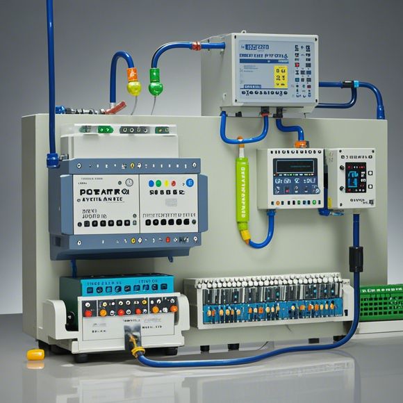
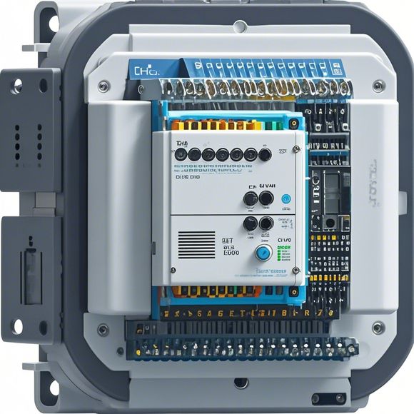
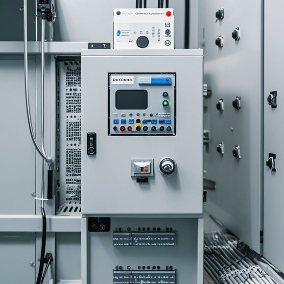
The PLC Controller Wiring Diagram in English is a diagram illustrating the connections between different electrical components in a Programmable Logic Controller (PLC). This diagram typically includes the input and output terminals, sensors, actuators, and other control modules connected to the processor. Each component is labeled with its corresponding function or device name, such as "Input Sensor" or "Output Actuator." The wiring diagram is essential for understanding how the PLC communicates with the outside world to control various industrial processes and machines.
As a foreign trade operations professional, understanding the wiring diagram of a PLC (Programmable Logic Controller) can help you better manage your industrial automation system. The following is a detailed guideline on how to read and interpret this wiring diagram:

1、Firstly, familiarize yourself with the basic components of a PLC controller. A typical PLC controller typically includes the CPU module, input/output modules (I/O), communication modules, and other peripherals. Each of these components plays a crucial role in the operation of the system.
2、Study the wiring diagram carefully and pay attention to the connections between the various components. Pay special attention to the power and control signals that are used to control the system. These signals may include digital signals (such as PWM signals or digital outputs), analog signals (such as voltage and current signals), and communication signals (such as RS485 or Ethernet).
3、Identify the functions of each component and their corresponding connections. For example, the CPU module is responsible for processing instructions and controlling the system, while the input/output modules are responsible for receiving data from sensors and transmitting control signals to actuators. The communication modules enable communication between the PLC controller and other systems, such as SCADA systems or HMIs.
4、Determine the power sources and grounding arrangements for each component. It is important to ensure that the power supply is stable and reliable, and that there is proper grounding to prevent electrical hazards.

5、Understand the logic flow of the system. A typical PLC controller has several logic blocks that control different functions of the system. By analyzing the wiring diagram, you can determine the sequence and connection of these blocks.
6、Analyze the programming requirements of the system. Different industries and applications may have specific requirements for programming languages and algorithms. You need to understand these requirements to write appropriate program codes for the PLC controller.
7、Communicate with technical experts or consult relevant manuals to gain more knowledge about the specific PLC controller model and its wiring diagram.
In summary, understanding the wiring diagram of a PLC controller requires careful analysis and practice. By studying it, you can effectively control the operation of your industrial equipment and optimize production efficiency.

Content expansion reading:
Articles related to the knowledge points of this article:
How to Use a PLC Controller for Your Business
PLC (Programmable Logic Controller) Control System Basics
Plumbers Rule! The Role of PLC Controllers in the World of Waterworks
Connecting a PLC Controller to Your Computer
PLC Controllers: A Comprehensive Guide to Understanding Their Prices