Introduction to PLC Control Cabinet Wiring Diagrams
PLC (Programmable Logic Controller) control cabinets are essential in modern industrial automation. They're used to manage and control the operation of various equipment, such as motors, valves, and sensors. The wiring diagram is a crucial document that outlines how these components are connected.The purpose of a wiring diagram for an PLC control cabinet is to illustrate the electrical connections between various components. It helps in troubleshooting issues and ensures that the system functions as expected.When creating a wiring diagram for an PLC control cabinet, it's important to follow proper electrical safety practices. This includes ensuring that all wires are properly labeled and not exposed, and that the circuit board is securely mounted.In conclusion, wiring diagrams for PLC control cabinets are essential for ensuring safe and efficient operation of industrial systems. With proper design and implementation, they can help prevent errors and ensure that the system performs as intended.
As a foreign trade operations manager, it's crucial for you to understand how PLC (Programmable Logic Controller) control cabinets are wired and connected. This understanding is fundamental in ensuring that your machinery operates smoothly and efficiently. In this guide, we will delve into the details of how these wiring diagrams work, covering everything from basic connections to advanced functions. So let's get started!

Firstly, let's talk about what a PLC control cabinet is. It’s essentially an enclosed box designed to control various mechanical systems, including pumps, fans, motors, and more. The key component inside the cabinet is the PLC (Programmable Logic Controller), which is a microprocessor-based device that can be programmed with different logic algorithms to perform tasks such as monitoring, controlling, and adjusting processes automatically.
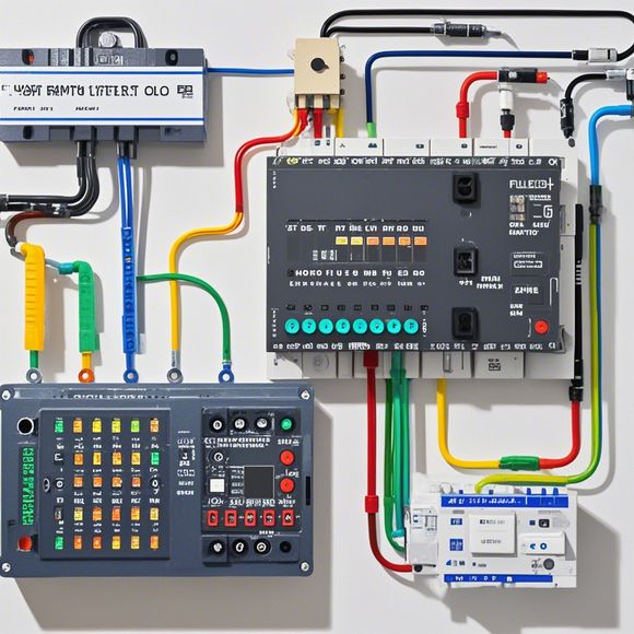
Now, let's talk about the importance of wiring diagrams in the PLC control cabinet. These diagrams show you exactly how the electrical components are connected together. They provide clear visual representations of the circuitry, helping engineers and technicians understand the system better and ensure that everything works as intended.
When looking at a wiring diagram, there are several key points to note. One is the main power input, which is typically marked as “AC” or “DC” depending on the type of power supply. Next, look for labels indicating the voltage and current ratings of each component, as well as any other relevant information.
The diagram should also show the connections between different components, like switches, sensors, and actuators. You'll see lines labeled "hot" or "neutral", which indicate where power is coming in or going out. Additionally, you'll find symbols such as "120VAC" or "5A" to denote specific details about the connection.

Another essential aspect of the diagram is its layout. Most modern wiring diagrams follow a standardized format, which includes sections for inputs, outputs, and internal connections. This helps make it easy to identify and troubleshoot problems quickly.
Now, let us dive into the specifics of how we connect our PLC control cabinet. Assuming we have a typical 4-input 1-output configuration, we would start by connecting the power source to the appropriate terminal on the control cabinet. We would then connect the AC power line directly to one of the input terminals, and the DC power line to another input terminal.
Next, we would install the sensors and switches that control the operation of the machine. For instance, if we want to turn on a fan when it reaches a certain temperature, we would attach a thermostat sensor to one of the input terminals and connect it to the fan's control signal.
Once all the components are connected, we would review the wiring diagram to ensure that everything is properly labeled and marked. If we notice any discrepancies or missing details, we would adjust them accordingly before completing the installation.

Finally, we would test the system to make sure everything is functioning correctly. This involves turning on the power supply and observing the output signals to verify that they are responding as expected. If something seems off, we would troubleshoot the problem by checking the connections or consulting with a professional engineer.
In summary, wiring diagrams play an important role in the operation of PLC control cabinets. By following proper guidelines and procedures, we can ensure that our machines are safe, reliable, and efficient. So remember to always read and understand your wiring diagrams carefully before starting any project or maintenance work.
Content expansion reading:
Articles related to the knowledge points of this article:
How to Use a PLC Controller for Your Business
Plumbers Rule! The Role of PLC Controllers in the World of Waterworks
The Role of Programmable Logic Controllers (PLCs) in Foreign Trade Operations
PLC Controllers: A Comprehensive Guide to Understanding Their Prices