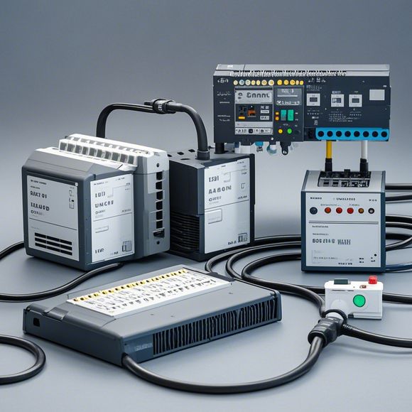
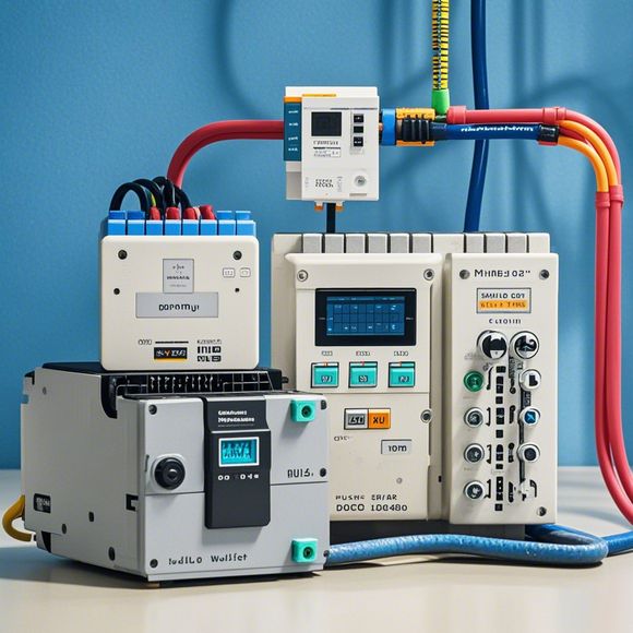
plc控制系统原理图
The PID control system's schematic drawing is a diagram that illustrates the components and connections within an industrial automation system.Before connecting, it’s crucial to thoroughly read and understand the design intent of the drawing, rather than relying on personal experience for wiring. If any uncertainties or contradictions are found, they should be promptly communicated with the designer to ensure no issues arise during the connection process.When wiring, it is essential to maintain clarity and orderliness in the steps involved, ensuring each step can be inspected and verified. This ensures the reliability and safety of the entire system. Utilize specialized tools such as wire strippers, connectors, and crimpers when necessary to ensure proper connections without causing damages like loosening or sharp edges.Learning from professionals, utilizing the correct tools for the job, and being mindful of the complexity of the PLC system can greatly enhance the efficiency and reliability of industrial applications. For instance, understanding how to properly use Q-box terminals, adapting to different types of PLC modules, and handling the connection between multiple modules are all important aspects to consider.In summary, mastering the construction and management of PID control systems through careful reading, precise wiring, learning professional skills, and understanding the complexities involved is key to ensuring the reliability and safety of industrial automation applications.
"Mastering the Art of Managing PLC Control Systems with a Deep Dive into Their Principles, Design, and Applications"
Introduction:
Hello everyone, today I am thrilled to be here with each of you to share some insights and knowledge about one of the most important components in modern manufacturing systems—the Programmable Logic Controller (PLC). So, let's start off with the basics.
PLC stands for "Programmable Logic Controller," and it has been a revolutionary advancement in industrial automation. These devices are designed to control and monitor processes, often used in factories, refineries, and other industrial settings where precise timing and accurate execution of tasks are crucial.

Now, let's delve into the world of PLCs, exploring their core principles, how they work, and how we can effectively manage them in our operations.
1、What is PLC?
PLC stands for Programmable Logic Controller. These are sophisticated digital electronic devices that can perform a wide variety of functions, such as controlling motors, monitoring temperature, or sensing process parameters. The term "programmable" means that these controllers are designed to execute instructions written in a specific language called "Ladder Diagrams" or "Block Diagrams."
2、How do they work?
PLCs operate based on a series of instructions stored in memory chips. When a signal is detected, the PLC reads the corresponding instruction from its memory, executes it, and then stores the result back into its memory. This process repeats until the task is completed, allowing for precise control over the system.
3、What are the different types of PLCs?
PLCs come in various forms, but the most common are the Basic Input/Output Module, Extended Input/Output Module, and Embedded System PLC modules. Each type is tailored for different applications and requirements. For example, the Basic Input/Output Module is designed to handle simple logic and control tasks, while the Embedded System PLC modules are ideal for complex systems requiring high-performance computing.
4、The Power of Ladder Diagrams and Block Diagrams
The key to programming any PLC lies in understanding the concept of "Ladder Diagrams" or "Block Diagrams." These visual representations of the program flow enable engineers and technicians to easily understand the logic behind the code and troubleshoot issues more quickly.
5、Applications of PLCs in Industry
PLCs have revolutionized the manufacturing industry by providing reliable and efficient control systems. They're used for everything from assembly lines to robotic arms to process monitoring systems. By leveraging PLCs, businesses can optimize production, reduce downtime, and improve overall efficiency.
6、The Importance of Maintenance and Optimization
Just like any other piece of hardware, PLCs require regular maintenance to ensure optimal performance. This includes checking for faulty wiring, software updates, and hardware replacements as needed to keep the system running smoothly. It's also essential to regularly optimize the code within the PLC, ensuring that it runs at its peak efficiency.
7、Case Study: A Successful PLC Application
One company that has made significant strides in utilizing PLCs is the automotive sector. By implementing PLC controls in their assembly line, they were able to streamline their operations, reduce downtime, and ultimately increase profitability. By using PLCs to monitor temperatures, pressure, and other critical parameters, they were able to maintain consistent levels of quality control throughout the entire production process.
8、Conclusion
Mastering the art of managing PLC systems requires a deep understanding of their core principles, design, and application. With proper planning, implementation, and maintenance, PLCs can be a valuable tool in your business's quest for efficiency and success. So, don't be afraid to get your hands dirty and dive deep into the world of PLCs. You'll be amazed at what you discover!
Content expansion reading:
Content:
Hey there! If you're new to the world of PLCs (Programmable Logic Controllers), or you're looking to brush up on your knowledge, understanding PLC control system wiring diagrams is a crucial step. These diagrams are the blueprint that tells you how all the components of a PLC system are connected and how they work together. In this post, we're going to dive in and break down what you need to know to make sense of these diagrams.

First things first, let's talk about what a PLC actually does. A PLC is a type of industrial computer designed to control and automate various electromechanical processes. It's like the brain of a machine, receiving input from sensors and switches, processing that information according to pre-programmed instructions, and then outputting control signals to actuators and other devices.
Now, let's get into the nitty-gritty of those wiring diagrams. A typical PLC control system wiring diagram will show you the following:
1、Power Supply: This is the source of electrical power for the PLC. It's usually a 24-volt DC supply, but can also be AC depending on the system.
2、PLC Unit: This is the heart of the system. It's where the logic and decision-making happen. The diagram will show the input and output modules connected to the PLC.
3、Input Devices: These are the sensors, switches, and other devices that provide data to the PLC. They're usually connected to the input modules.
4、Output Devices: These are the actuators, motors, and other devices that the PLC controls. They're connected to the output modules.
5、Relay Logic: If the system has relays, the diagram will show how they're connected to the PLC and other devices. Relays are like electrical switches that can control higher voltage or current devices.
6、Control Panel: This is the user interface where you can monitor the system and make adjustments. It might include buttons, switches, and a display.
7、Wiring: The diagram will show the actual wiring between all the components, including the wire type and length if specified.
When you're looking at a PLC control system wiring diagram, it's important to pay attention to the symbols used. Each component has a specific symbol, and the wiring is represented by lines with arrows that indicate the direction of the electrical flow.
Here's a quick rundown of some common symbols you'll see:
PLC: A rectangular box with the manufacturer's name or model number.
Input: A triangle or a circle with a line coming out of it, representing a sensor or switch.
Output: A rectangle with a line coming out of it, representing an actuator or motor.
Relay: A box with a number of contacts inside, indicating different switching possibilities.
Power Supply: A symbol that looks like a battery or a power plug.
Remember, the key to understanding these diagrams is to look for the flow of information and power. Inputs provide data, the PLC processes that data, and outputs carry the control signals.
If you're new to PLCs, don't be intimidated by the complexity of these diagrams. They can seem overwhelming at first, but with a bit of practice and a good understanding of the basic components, you'll be able to read and interpret them with ease. Always refer to the manufacturer's manual for specific details and safety information.
So there you have it! A quick guide to help you get started with understanding PLC control system wiring diagrams. Whether you're a seasoned pro or just starting out, this knowledge will serve you well in the world of industrial automation.
Articles related to the knowledge points of this article:
PLC Controller Selection Guide for Foreign Trade Operations
PLC Programming for Automation Control in the Manufacturing Industry
PLC (Programmable Logic Controller) Control System Basics
Plumbers Rule! The Role of PLC Controllers in the World of Waterworks
The Role of Programmable Logic Controllers (PLCs) in Foreign Trade Operations