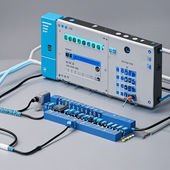
PLC Control Input-Output Mapping Guide
This PLC Control Input-Output Mapping Guide is your comprehensive guide to understanding how input-output mapping works in Programmable Logic Controllers (PLCs). By following this manual, you'll be able to effectively manage your system's inputs and outputs, ensuring smooth operations of your industrial or manufacturing processes. The detailed steps outlined in this manual will help you identify, connect, and map the correct inputs and outputs for your specific application. With this tool at your disposal, you can streamline your operations and optimize your system's performance.
As an experienced foreign trade operator, I am responsible for maintaining and updating the PLC (Programmable Logic Controller) input/output (I/O) mapping chart. This guide serves as a vital tool to ensure that our production lines are operating smoothly and efficiently, minimizing downtime and maximizing productivity.
The PLC input/output mapping chart is a crucial component of any automation system, as it provides the connection between the various components within the system. It enables us to program the logic in the PLC to control the flow of materials and processes, ensuring that everything runs smoothly and without errors.
In this guide, I will provide you with a step-by-step overview of how to create an effective PLC input/output mapping chart. We will start by identifying the various components that we need to control, such as sensors, actuators, switches, and relays. Then, we will map each component's inputs and outputs to the corresponding pins on the PLC.

To begin this process, gather all of the necessary components and connect them to the PLC. Once the components are connected, we can start mapping them using software or manually by connecting the appropriate pins together. Remember to label each pin clearly to avoid confusion during programming.
Once the mapping is complete, we can move on to the programming phase. Use the appropriate programming language and tools to code the PLC according to the I/O mapping chart. Be sure to test the program thoroughly before moving forward with production to ensure that everything works as expected.
Finally, monitor the performance of the PLC system regularly to ensure that it is functioning correctly. If there are any issues or problems, address them promptly to prevent downtime and maintain high levels of productivity.
In conclusion, creating an effective PLC input/output mapping chart is essential for maintaining smooth operation of any automation system. By following these steps and utilizing proper software and hardware, we can ensure that our manufacturing processes run at optimal efficiency and reduce downtime.
Content expansion reading:
Content:

Hey there, fellow automation enthusiasts! Today, we're diving into the world of Programmable Logic Controllers (PLCs) and exploring the nitty-gritty of input and output mapping. If you're new to PLCs or just looking to brush up on your knowledge, this guide is for you. So, let's get started!
PLCs are the brains of any automated system, controlling the flow of information and power between the system and the outside world. Inputs and outputs are the gateway to this information, and understanding how they work is crucial for any PLC operator.
Inputs are the eyes of the PLC, allowing it to "see" what's happening in the environment. These can be switches, sensors, or any other device that provides data to the PLC. When you're setting up your PLC, you'll need to map these inputs to specific addresses within the PLC's memory. This is where the Input Table comes in handy.
The Input Table is like a roadmap for the PLC, telling it where to look for input data. Each input device is assigned a unique address, and the table tells the PLC what to do with that data. For example, if you have a limit switch on a conveyor belt, you'll map that switch to an input address so the PLC knows when the belt is full or empty.
Outputs, on the other hand, are the hands of the PLC, controlling the physical world. They can be relays, solenoids, or any device that requires power to operate. The Output Table is where you map these devices to the PLC's outputs. Each output is given an address, and the PLC uses this table to know which device to activate or deactivate.
When programming your PLC, you'll use Ladder Logic or another programming language to create instructions. These instructions tell the PLC what to do with the input data and when to activate the outputs. The PLC then uses the input and output tables to execute these instructions.

It's important to note that different types of PLCs can have varying input and output configurations. Some PLCs may have discrete inputs and outputs, while others might support analog signals. Analog inputs can measure continuous variables like temperature or pressure, while analog outputs can control devices that require a continuous range of power, like heating elements.
To ensure your PLC is functioning correctly, you'll need to regularly check and maintain your input and output tables. This includes verifying that input devices are functioning properly and that output devices are responding as expected.
In conclusion, mastering the input and output mapping of a PLC is essential for effective automation. By understanding how to use the input and output tables, you can ensure that your PLC is communicating with the world around it efficiently and accurately. So, keep practicing, stay curious, and happy automating!
Articles related to the knowledge points of this article:
PLC Controller Selection Guide for Foreign Trade Operations
Mastering the Art of Plc Controllers: A Comprehensive Guide to Understand and Implement
PLC Programming for Automation Control in the Manufacturing Industry
How to Use a PLC Controller for Your Business
PLC (Programmable Logic Controller) Control System Basics
Plumbers Rule! The Role of PLC Controllers in the World of Waterworks