Mastering PLC Circuit Diagrams through a Comprehensive Guide
Title: Mastering PLC Circuit Diagrams through a Comprehensive GuideIntroduction:,For those working with Programmable Logic Controllers (PLC) in their daily routine, understanding and mastering the intricate circuit diagrams can be a daunting task. However, fear not! In this comprehensive guide, we'll provide you with an in-depth look at the key elements of PLC circuit diagrams, ensuring that you have a thorough grasp of their structure and functionality.Key Points:,1. **Understanding the Basics**: Start by familiarizing yourself with the basic components of a PLC circuit diagram, including sensors, actuators, relays, and switches. Each component plays a critical role in the overall functionality of the system.2. **Identifying the Inputs and Outputs**: Pay close attention to the inputs and outputs present in each circuit diagram. These are the primary means through which the system interacts with the outside world.3. **Analyzing the Signals**: Study the signals present in each section of the circuit diagram. Understand the different types of signals (e.g., digital or analog) and how they are transmitted and processed within the system.4. **Learning About PLC Programs**: Explore the different programming languages used in PLC systems. Understanding these languages can significantly enhance your ability to troubleshoot and modify existing circuit diagrams.5. **Practical Application**: Try to simulate various scenarios using your newfound knowledge. This will not only improve your understanding but also make the learning experience more enjoyable.Conclusion:,Mastering PLC circuit diagrams is a crucial skill for anyone working with PLC systems. By following the steps outlined in this comprehensive guide, you can quickly gain the necessary expertise to confidently navigate the complexities of PLC circuit diagrams. Remember, practice makes perfect, so don't hesitate to put these skills into action!
Introduction:
In the realm of international trade, understanding the complexities of PLC (Programmable Logic Controller) circuit diagrams is essential for navigating the technical jargon and ensuring successful operations. This comprehensive guide aims to simplify the process of deciphering PLC circuit diagrams, offering a clear and concise approach that will enable you to navigate even the most intricate schematics with ease.
Key Points:

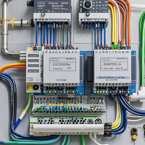
1、Understanding the Basics: Begin by familiarizing yourself with the basic components of a PLC circuit diagram. These include the input/output modules, processors, memory, and various sensors and actuators. Each component plays a crucial role in the overall functionality of the system.
2、Reading and Recognizing Signals: The key to interpreting a PLC circuit diagram lies in recognizing the signals and their corresponding functions. Look out for the different color codes and labels that indicate the type of signal being conveyed. This knowledge will help you differentiate between different types of signals and understand their interplay within the system.
3、Identifying Circuit Connections: Once you've identified the signals, focus on the connections between them. Pay close attention to the wiring diagrams and identify the various wires and terminals that connect different components. This knowledge will be crucial when troubleshooting or modifying the system.
4、Understanding Logic Functions: A PLC circuit diagram typically includes a series of logical functions that dictate how the system operates. Familiarize yourself with these functions, such as sequence control, logic decision-making, and data processing, as they form the backbone of any PLC system.
5、Practical Tips: To further your understanding, consider practicing by analyzing actual schematics. This can be done by consulting with professionals in the field or using online resources that offer step-by-step tutorials on interpreting PLC circuit diagrams. Additionally, attending workshops or training sessions can provide valuable insights into real-world scenarios and best practices for working with PLC systems.
Conclusion:
Navigating the world of international trade requires mastery over complex technical processes, including PLC circuit diagrams. By following the steps outlined above, you'll be well on your way to deciphering even the most intricate schematics with ease. Remember, practice makes perfect - the more you analyze schematics, the easier it becomes to recognize patterns and make informed decisions. So, dive in, and let your skills soar!
Content expansion reading:

Content:
Hey there, fellow tech enthusiasts! Today, we're diving into the world of Programmable Logic Controllers (PLCs) and how to make sense of those complex circuit diagrams that often come with them. Don't worry, even if you're new to the game, I'll break it down for you in a way that's easy to digest. So, let's get started!
First things first, what is a PLC? Think of it as a brain for machines. It's a digital computer designed to control and automate industrial electromechanical processes. PLCs are used in a wide range of industries, from manufacturing to power generation, and they're super versatile.
Now, let's talk about those circuit diagrams. They're like the language that PLCs speak, and they can be a bit intimidating at first glance. But once you know the basics, it's like unlocking a secret code. Here's a quick rundown of what you need to know:
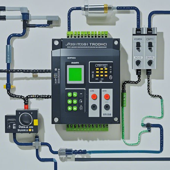
1、Inputs and Outputs: These are the heart of the PLC circuit. Inputs are the signals that the PLC receives from sensors or switches, while outputs are the signals that the PLC sends to actuators or other devices.
2、Logic Gates: These are the decision-makers. They use logic to determine whether an output should be turned on or off based on the inputs. The most common types are AND, OR, and NOT gates.
3、Timers and Counters: These are used to control the duration or frequency of outputs. Timers can be set to turn on or off after a certain time delay, while counters can be used to count events or pulses.
4、Control Logic: This is where the magic happens. It's the set of instructions that the PLC uses to make decisions and control the process. Ladder logic is the most common type and it's designed to look like relay logic, which is easy for electricians to understand.

5、Power Supply: This is the source of power for the PLC and its components. It's important to have a stable and clean power supply to ensure the PLC operates correctly.
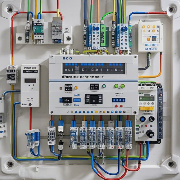
6、Wiring: This is the nervous system of the PLC. It connects all the components together and can be color-coded to indicate different types of signals.
Now, let's look at a simple PLC circuit diagram. Imagine you've got a machine that needs to be turned on only when two switches are pressed at the same time. Here's how the diagram might look:
Inputs:
- Switch 1
- Switch 2
Output:
- Motor
Logic:
- AND Gate: Connects Switch 1 and Switch 2. Output is active only when both switches are pressed.
- Relay: Connects the AND Gate output to the Motor.
Wiring:
- Red wires indicate power, black wires indicate control signals, and blue wires indicate ground.
In this example, when Switch 1 and Switch 2 are both pressed, the AND Gate activates, which in turn powers the Relay. The Relay then connects the power to the Motor, and voila, the machine starts.
Remember, PLCs are all about safety and reliability. Always follow the manufacturer's guidelines when setting up or troubleshooting a PLC circuit. And if you're ever in doubt, consult with a professional.
That's it for today! I hope this quick overview has given you the confidence to tackle those PLC circuit diagrams with ease. Happy automating!
Articles related to the knowledge points of this article:
Mastering the Art of Plc Controllers: A Comprehensive Guide to Understand and Implement
PLC Controller for Manufacturing Automation
PLC Programming for Automation Control in the Manufacturing Industry
PLC (Programmable Logic Controller) Control System Basics
Plumbers Rule! The Role of PLC Controllers in the World of Waterworks