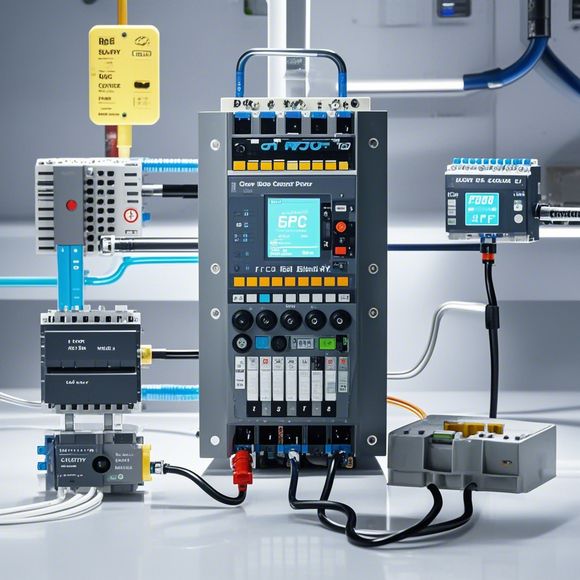
PLC Module Wiring Diagram
Sure, here's a summary of your content in an informal English format:PLC (Programmable Logic Controller) modules are used in industrial automation systems to perform various tasks like controlling machines, monitoring process variables, and managing data. Wiring diagrams represent how these modules are connected to each other, as well as to the external devices they control. They show the electrical connections between components, such as sensors, actuators, input/output interfaces, and communication lines. The wiring diagram helps in ensuring that all components are correctly connected and functioning together, which is crucial for maintaining the stability and efficiency of the system.
Dear all, today I would like to introduce our company's PLC module wiring diagram, which is an essential tool for ensuring the smooth operation of our industrial automation system.

Firstly, the PLC module wiring diagram is a visual representation that shows the connections between the various components of the system. It includes information about the input and output devices, sensors, switches, and other control devices. This diagram helps us understand the relationships between different components and how they work together to achieve specific functions. It also provides us with valuable insights into potential issues or failure points in the system, allowing us to troubleshoot and fix problems more quickly.
Secondly, the PLC module wiring diagram helps us maintain and upgrade the system over time. By reviewing the diagram regularly, we can identify areas that require maintenance or replacement of components. This can save us money in the long run by avoiding costly repairs or replacements caused by faulty wiring. Additionally, it allows us to update the system with new features or improvements that enhance its performance and efficiency.
Thirdly, the PLC module wiring diagram is essential for training new employees on the system's operations. It provides them with detailed information about the various components and their functions, as well as how they interact with each other. By understanding the wiring diagram, new employees can quickly become familiar with the system's layout and capabilities, reducing the chances of errors or mishaps during their work.
Fourthly, the PLC module wiring diagram is crucial when designing new systems or upgrading existing ones. By having access to this diagram, engineers can accurately plan and execute the necessary modifications without causing disruptions to production or operational activities. Additionally, it allows us to incorporate new features and capabilities into the system, such as adding more sensors or adjusting the settings of certain parameters, while still maintaining the overall functionality and stability of the system.
In conclusion, the PLC module wiring diagram is a critical component of our company's industrial automation system. It provides us with valuable information about the system's components and their interactions, helping us maintain, upgrade, train employees, and design new systems. Without it, we risk losing control over the system's functioning, leading to downtime, increased costs, and potential safety hazards. Therefore, let's make sure that this diagram is always up-to-date and accurate, so we can continue to rely on it for our success as a business. Thank you!
Content expansion reading:
Content:
Hey there! If you're new to the world of PLCs (Programmable Logic Controllers), or you're just looking to brush up on your knowledge, understanding PLC module wiring diagrams is a crucial step. These diagrams can seem intimidating at first, but once you know what to look for, they're actually pretty straightforward.

PLC modules are the building blocks of a PLC system. They perform various functions, from simple on/off control to complex data processing. When these modules need to communicate with each other or with other devices, they do so through a wiring diagram that specifies how they should be connected.
A typical PLC module wiring diagram will show you the input and output points, power supply connections, and how the modules are interconnected. Inputs are represented by circles, while outputs are shown as squares. Power supply connections are usually represented by a + and - symbol, indicating the positive and negative terminals.
One of the most important things to remember when looking at a PLC module wiring diagram is that the inputs and outputs are not always physical connections. In some cases, they can be logical connections, meaning they're represented in the program but not necessarily by a physical wire.
When you're working with PLC modules, it's also important to understand the difference between discrete and analog inputs and outputs. Discrete signals are either on or off, while analog signals can vary continuously. This will be reflected in the wiring diagram, with discrete signals often being represented by a single line and analog signals by a squiggly line.
Another key aspect of PLC module wiring diagrams is the use of addressing. Each input and output point will have an address, which is how the PLC knows where to send and receive data. These addresses are usually in the form of numbers or letters and numbers combined.
If you're ever unsure about how to interpret a PLC module wiring diagram, don't hesitate to reach out to the manufacturer or consult the documentation that came with the PLC system. They should be able to provide you with all the information you need to understand and work with the wiring diagrams.
Remember, practice makes perfect. The more wiring diagrams you look at and work with, the more comfortable you'll become with interpreting them. So, grab a diagram and start exploring!
Articles related to the knowledge points of this article:
PLC Controller Selection Guide for Foreign Trade Operations
The cost of a PLC Controller: A Comprehensive Analysis
PLC Programming for Automation Control in the Manufacturing Industry
How to Use a PLC Controller for Your Business
Plumbers Rule! The Role of PLC Controllers in the World of Waterworks
The Role of Programmable Logic Controllers (PLCs) in Foreign Trade Operations