Understanding the PLC Circuit Diagram through a Picture: A Comprehensive Guide for Beginners
If you're a beginner and want to understand the PLC circuit diagram, then this comprehensive guide is just what you need. It's based on a picture, so you don't have to worry about reading text. The guide will walk you through each step of the process, from understanding the components to connecting them up. You'll learn how to read schematic symbols, recognize different types of relays, and identify wire colors. With this guide, you'll be able to build your own PLC circuit in no time. So grab your tools and get started!
As an experienced foreign trade operator, understanding PLC circuit diagrams is crucial for ensuring smooth operations and efficient production. Here's a comprehensive guide that will help you quickly grasp key concepts and features of PLC circuit diagrams.
Firstly, let's start by understanding what a PLC (Programmable Logic Controller) is. A PLC is an electronic device that can perform complex calculations based on input signals from various sensors and devices. It can be programmed to control various processes in industrial environments, such as temperature control, motion control, and process monitoring.
Now, let's move on to the key components of a PLC circuit diagram. The main components include the input/output ports, processing units, memory modules, and communication interfaces. The input/output ports are responsible for receiving and transmitting signals to and from various sensors and actuators. Processing units are used to analyze the input signals and generate appropriate output signals to control the process. Memory modules store the program code for the PLC and are essential for executing the program instructions. Communication interfaces allow the PLC to communicate with other systems in the industrial environment, such as HMI (Human Machine Interface) displays or SCADA (Supervisory Control And Data Acquisition) systems.
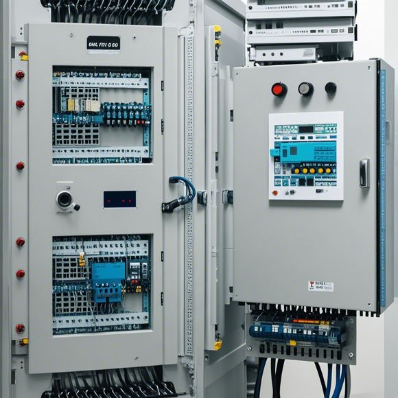
To understand the PLC circuit diagram more intuitively, we can use a picture to represent the components. For example, if there is a red square at the top left corner of the diagram, it represents the input port. If there is a blue square below it, it represents the output port. The green circle at the bottom right corner could represent the processing unit, while the yellow triangle next to it may signify communication interfaces.

To further enhance our understanding, let's take a step back and consider the overall structure of the PLC circuit diagram. The diagram typically consists of several layers, including the hardware layer, software layer, and data flow layer. The hardware layer includes the input/output ports, processing units, memory modules, and communication interfaces. These components are designed to work together seamlessly to achieve specific control objectives.
The software layer involves the embedded operating system and user programs developed for the PLC. These programs are responsible for managing the hardware resources, coordinating with other systems in the industrial environment, and performing calculations based on input signals. The data flow layer is responsible for transmitting the processed signals back to the control system for further processing.
In summary, a PLC circuit diagram is a critical component in industrial automation systems. By understanding the key components and their relationships, we can effectively manage and optimize production processes using PLCs. Whether you are a beginner or experienced operator, this guide provides valuable insights into mastering PLC circuit diagrams. Remember to practice regularly to gain deeper insights and become proficient in handling PLC circuits!
Content expansion reading:
Content:
Hey there, fellow tech enthusiasts! Today, we're diving into the world of Programmable Logic Controllers (PLCs) and how to make sense of those complex circuit diagrams. Don't worry, we're gonna break it down in a way that's easy to digest. So, let's get started!

First things first, what is a PLC? It's a type of industrial computer designed to control and automate various electromechanical processes. These processes can range from simple on/off control to complex data handling and motion control. PLCs are tough, they can handle harsh environments, and they're super reliable, making them the go-to choice for many industrial applications.
Now, let's talk about those circuit diagrams. They can look like a jungle of symbols and lines, but each part has a specific meaning. The heart of the PLC is the processor, which is where all the magic happens. It's responsible for executing the program that controls the system.
Around the processor, you'll see input and output devices. Inputs are like the eyes and ears of the PLC, they sense what's happening in the real world, like switches, sensors, or even data from other systems. Outputs, on the other hand, are the hands and feet. They take the decisions made by the processor and act on them, controlling actuators, motors, or even other PLCs.
The brain of the PLC communicates with these devices through input/output (I/O) modules. These modules translate the electrical signals from the devices into data that the PLC can understand, and vice versa.
One key concept in PLC circuit diagrams is the ladder logic. This is the programming language of PLCs, and it's designed to be easy to read and understand, even for those without a programming background. Ladder logic is made up of rungs, which are composed of input and output contacts, and logic operators that tell the PLC what to do.
When you're looking at a PLC circuit diagram, remember that the top rail is typically the power supply, and the bottom rail is ground. The rungs in between are the logic that tells the PLC when to turn things on and off.

Now, here's a pro tip: to understand a PLC circuit diagram, start by identifying the power supply. Then, look for the inputs and outputs. Finally, trace the ladder logic to see how the inputs and outputs are connected and what conditions must be met for the outputs to activate.
Remember, practice makes perfect. The more you look at PLC circuit diagrams, the more you'll start to see the patterns and understand the flow of the logic. It's like learning a new language; at first, it's overwhelming, but with time and dedication, it becomes second nature.
So, there you have it! A quick and easy guide to understanding PLC circuit diagrams. Whether you're a seasoned pro or just starting out, these tips should help you make sense of even the most intricate PLC setups. Happy troubleshooting, and keep those circuits flowing!
Articles related to the knowledge points of this article:
Smart Manufacturing Solutions with PLC Integrated Machinery
Connecting a PLC Controller to Your Computer
PLC Controllers: A Comprehensive Guide to Understanding Their Prices
Effective Strategies for Handling PLC Control System Faults
What is a Programmable Logic Controller (PLC)
PLC Controller Advantages: A Comprehensive Guide for Success in Global Trade