Mastering the Art of PLC (Programmable Logic Controller) Wiring
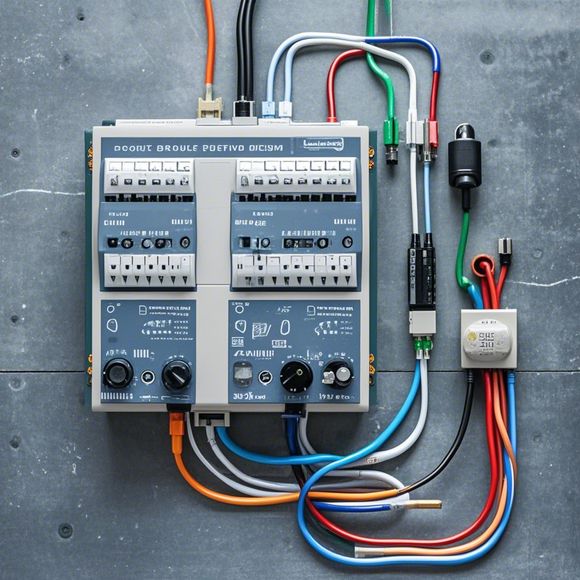
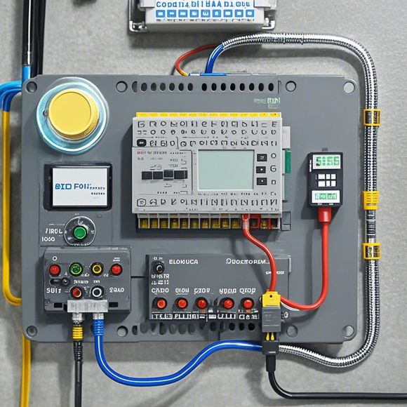
Sure, I can certainly help with that! Let's break down the task into smaller steps and then summarize them in a way that is easy to understand.**Step 1: Understanding the Basics**Before we dive into the specifics of wiring a PLC (Programmable Logic Controller), it's important to have a good understanding of what a programmable logic controller is and what its main functions are. A PLC is a powerful tool used in industrial automation systems for controlling complex processes and systems. It's essentially a computer that can be programmed to perform tasks based on instructions written in special programming languages.**Step 2: The Basics of Wiring**Once you know what a PLC is, the next step is to understand how it is wired. There are three primary components of a PLC – the CPU (Central Processing Unit), which contains all the software and hardware necessary to control the system; the RAM (Random Access Memory), which stores data temporarily until needed; and the power supply unit, which provides power to the PLC.**Step 3: Wiring Techniques**Wiring a PLC involves connecting different components together according to the manufacturer's guidelines. Common techniques include using cables labeled with pin numbers to connect the PLC's various inputs and outputs to other components in the system. It's important to ensure that connections are secure and properly labeled to avoid any errors or issues during the operation.**Conclusion**In conclusion, mastering the art of wiring a PLC requires a solid understanding of its functions and components, along with proper knowledge of the appropriate wiring techniques. By following established procedures and guidelines, you can confidently install and maintain a functional PLC system in your industrial environment.
As a seasoned外贸运营, understanding how to effectively wire PLCs (Programmable Logic Controllers) is essential for ensuring smooth operation and troubleshooting. In this guide, we will dive into the intricacies of plc input and output wiring, providing insights into various aspects such as the types of connections, the importance of signal strength, and the benefits of using dedicated wiring methods. By following these tips, you can ensure that your PLC system runs efficiently and reliably.
Firstly, let's delve into the different types of connections required for PLC input and output wiring. There are two primary methods: direct wiring and via-hole wiring. Direct wiring involves connecting wires directly to individual PLC pins. This method provides a high degree of flexibility and allows for precise control of the signal path. On the other hand, via-hole wiring involves placing a connector on each end of the wire and connecting them to the appropriate pins through an intermediary component. This method is often used when space constraints or complex wiring arrangements are required.
When it comes to selecting the correct type of connection, it is crucial to consider factors such as the voltage and current requirements of the circuit, as well as the distance between the PLC and the source or destination of power. For example, if you are working with low-voltage signals, using a differential pair connection is recommended to reduce noise and improve signal integrity. Additionally, if there is a significant physical distance between the PLC and the device requiring power, a power filter or isolation transformer may be necessary to ensure safe operation.
Another important factor to consider is the choice of wire gauge and insulation material. Wires must be chosen according to the voltage level and current capacity required for the application. High-quality insulation materials such as polyester or PVC should be used to prevent moisture or heat damage, which can cause electrical shorts or fire hazards.

In terms of wiring techniques, there are several options available depending on the specific needs of your project. One common method is to use a shielded cable, which helps to minimize electromagnetic interference (EMI) and protect sensitive electronic components. Another option is to use twisted pairs or stripped wires for high-speed data transmission, as they provide greater bandwidth and reliability than unshielded wires. Additionally, using a balanced connector can help to eliminate common mode noise and improve signal quality.
It is also important to consider the placement of the PLC within the wiring system. Proper spacing between components and avoidance of overheating zones are critical to preventing failure due to excessive heat. Additionally, using a dedicated wiring method like a bus bar or a star configuration can simplify installation and maintenance processes while improving signal integrity.
One common mistake made by newbies is attempting to connect all the wires directly to a single PLC pin. While it may seem like an easy fix, this approach can lead to potential short circuits and other electrical issues down the line. Instead, it is better to use a jumper or a switch box to safely disconnect and reconnect individual wires without risking damage to the PLC.
Another consideration when wiring PLCs is the need for power distribution. If multiple devices require power from the same source, consider using a power distribution unit (PDU) that can manage voltage and current levels more efficiently than a standalone switch or relay. This ensures that the power supply remains stable and reliable throughout the entire system.
In addition to the technical aspects of wiring, it is also important to consider safety regulations when working with PLCs. Ensure that all wiring is done in accordance with local electrical codes and standards, such as those outlined by Underwriters Laboratories (UL) or ENERGY STAR. Proper documentation should be kept on all wiring work, including drawings, schematics, and any test results.
Finally, don't forget to test your PLC system before finalizing the wiring design. Use a multimeter to check for continuity, insulation resistance, and voltage levels across all connections. Additionally, perform functional tests to ensure that the circuit operates correctly and meets the desired functionality. Remember to follow the manufacturer's instructions for testing and troubleshooting.
In conclusion, mastering PLC input and output wiring requires a combination of knowledge, skill, and attention to detail. From choosing the right type of connections to implementing proper wiring practices and testing procedures, every step contributes to the success of your PLC system. By following these guidelines and staying informed about the latest trends and technologies in automation, you can ensure that your PLC wiring projects are both reliable and efficient.
Content expansion reading:
Content:

Hey there! If you're new to the world of PLCs (Programmable Logic Controllers), one of the first things you'll need to wrap your head around is how to interpret those complex input and output wiring diagrams. Don't worry, it's not as daunting as it seems! Let's break it down in a way that's easy to understand.
First things first, what is a PLC? It's a type of industrial computer that's designed to control and automate various types of machinery and processes. The heart of a PLC is its I/O (Input/Output) system, which is what we're going to focus on today.
An I/O wiring diagram is a blueprint that shows how the PLC is connected to the devices it controls or monitors. Inputs are the signals that the PLC receives from sensors, switches, or other devices, while outputs are the signals that the PLC sends to actuators, motors, or other devices to control them.
Here's a simple step-by-step guide to help you understand a PLC I/O wiring diagram:
1、Identify the Components: Look at the diagram and find the symbols for inputs and outputs. Inputs might be represented by switches, while outputs could be represented by lights or motors.
2、Understand the Symbols: Each component in the diagram will have a specific symbol. Make sure you understand what each symbol means. For example, a switch might have an open or closed position, which will correspond to a binary input (on or off) for the PLC.
3、Read the Labels: Every input and output should be labeled. These labels tell you what the specific input or output is for, such as "Emergency Stop Switch" or "Motor Start Relay."
4、Follow the Wires: Connections between components are shown by wires. These wires represent the electrical path between the devices and the PLC.
5、Check the Addresses: Each input and output will have an address assigned to it. This is how the PLC knows where to look for the signal. Make sure you note down these addresses for future reference.

6、Consider the Type of Signal: Different inputs and outputs can use different types of signals, like digital or analog. Digital signals are typically on/off, while analog signals can vary in strength.
7、Look for Power Supplies: Make sure you understand where the power is coming from and how it's being distributed to the different components.
8、Check for Grounding: Proper grounding is essential for safety and to prevent electrical noise. Look for ground symbols in the diagram.
9、Review the Control Logic: The control logic is the set of rules the PLC uses to determine when to turn on or off an output. This is usually represented by ladder logic or another programming language.
10、Seek Professional Help if Needed: If you're still confused, don't hesitate to reach out to a professional or consult the manufacturer's manual for your PLC.
Remember, practice makes perfect. The more wiring diagrams you look at, the better you'll become at interpreting them. Always double-check your work to ensure that you're not missing anything and that the diagram makes sense in the context of the system you're working with. Safety is paramount, so take your time and understand the implications of any changes you might make based on the wiring diagram.
Articles related to the knowledge points of this article:
PLC Programming for Automation Control in the Manufacturing Industry
How to Use a PLC Controller for Your Business
Plumbers Rule! The Role of PLC Controllers in the World of Waterworks
The Role of Programmable Logic Controllers (PLCs) in Foreign Trade Operations
Connecting a PLC Controller to Your Computer
PLC Controllers: A Comprehensive Guide to Understanding Their Prices