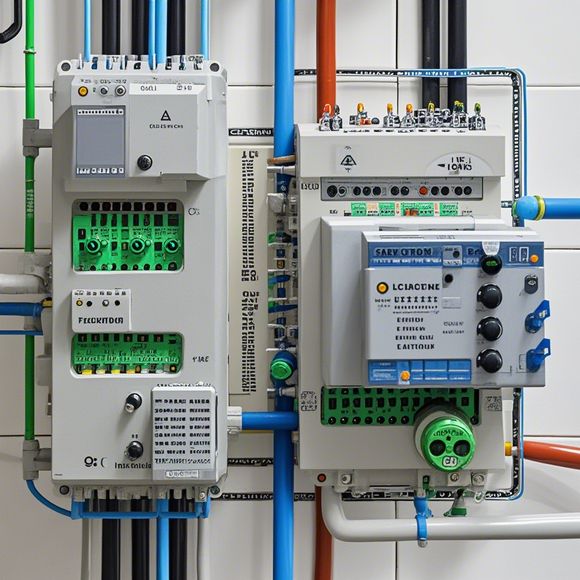
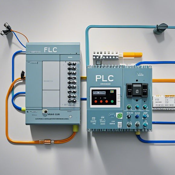
PLC Controller Wiring Diagram
Sure, I can help you create a concise summary of the content you've given me in English:PLC (Programmable Logic Controller) Controller Wiring Diagram:This diagram illustrates the wiring connections for an PLC controller. It consists of several components, including input and output ports, power supply lines, and communication interfaces such as Ethernet or RS232. The diagram also shows the connections between these components, indicating which wires are used for each connection point.The wiring diagram is important because it helps to ensure that the correct electrical connections are made for the PLC controller to communicate with other devices and perform its tasks effectively. Without proper wiring, there could be issues with signal loss, interference, or even damage to the PLC controller itself.Overall, the PLC controller wiring diagram provides a clear overview of how the various components are interconnected and connected to each other for optimal performance.
As an experienced外贸运营, it is crucial for me to have a clear understanding of the plc controller wiring diagram. The plc (programmable logic controller) controller is an essential component in many industrial applications, such as manufacturing processes, automation systems, and robotics. A well-designed wiring diagram helps to ensure that the plc operates smoothly and efficiently, reducing downtime and improving overall productivity. In this guide, we will provide an overview of the key components involved in the plc controller wiring diagram, their functions, and how to connect them properly according to the manufacturer's specifications.
The first step in creating a successful plc controller wiring diagram is to understand the basic components involved. These include the input/output devices, processors, memory, communication interfaces, power supplies, and safety features. Each component has its specific function and must be connected correctly to ensure seamless operation.

One important aspect of the wiring diagram is the selection of appropriate cable types and connectors. High-speed Ethernet connections are commonly used for data transmission between the plc processor and other network devices, while power cords and switches provide the necessary voltage and current to operate the controller. Additionally, grounding should be established to prevent electromagnetic interference and protect personnel from electrical shock.
In addition to hardware connections, software configuration is also critical in ensuring proper functionality. The user interface allows for easy monitoring and adjustment of settings such as program start/stop times, alarm limits, and diagnostic modes. Debugging options can be enabled for troubleshooting issues during system testing.
To optimize performance and reduce costs, it is important to consider factors such as energy efficiency and reliability. This may involve using low-power components or implementing energy-saving strategies such as reducing standby mode time and minimizing idle cycles. It is also essential to regularly test the wiring diagram to identify any faults or deviations from the manufacturer's specifications.
In conclusion, creating a successful plc controller wiring diagram requires a comprehensive understanding of the components involved, careful consideration of hardware and software configuration, and ongoing monitoring and testing to ensure optimal performance. By following these steps and addressing potential concerns, you can establish a reliable and efficient plc control system that meets your business's requirements.
Content expansion reading:
Content:
Hey there! If you're new to the world of PLCs (Programmable Logic Controllers), or you're just looking to brush up on your knowledge, understanding PLC controller wiring diagrams is a crucial step. These diagrams can seem intimidating at first, but once you know what to look for, they're actually pretty straightforward.
So, let's dive in and break down what a PLC controller wiring diagram is and how to interpret it.
First things first, a PLC controller wiring diagram is a visual representation of the electrical connections between the various components of a PLC system. It shows you how the PLC is connected to input devices (like sensors), output devices (like actuators), and other peripheral equipment. The diagram is designed to help you understand the flow of information and power within the system.

When you're looking at a PLC controller wiring diagram, you'll typically see a few key elements:
1、PLC Module: This is the heart of the system. It's where the programming and logic take place.
2、Input Devices: These are the things that tell the PLC what's going on in the system. Think of them as the eyes and ears of the PLC. Examples include limit switches, temperature sensors, and push buttons.
3、Output Devices: These are the muscles of the system. They carry out the actions that the PLC tells them to. Examples include motors, solenoids, and lights.
4、Power Supplies: These are what keep the system running. They provide the necessary voltage and current to the PLC and other components.
5、Wiring: The actual physical connections between all these components.
Now, let's talk about how to read a PLC controller wiring diagram. Here are some tips:
Start with the Power Supply: Look for the power supply symbol and note the voltage and amperage ratings. This will give you an idea of the system's power requirements.
Follow the Flow: Trace the wiring from the power supply to the PLC, then from the PLC to the input devices, and finally from the PLC to the output devices.

Identify the I/O Points: Inputs (I) and outputs (O) are usually clearly labeled on the diagram. Match these with the corresponding devices in the real-world setup.
Check the Symbols: Each component has a specific symbol, and the wiring diagram will use these to represent different devices. Make sure you understand what each symbol means.
Read the Legend: Every wiring diagram should have a legend that explains what each symbol represents. Use this as a reference if you're unsure about a particular component.
Remember, the key to understanding PLC controller wiring diagrams is to take it slow and methodically work your way through the diagram. With a bit of practice, you'll be able to interpret these diagrams like a pro!
If you're new to PLCs or need more in-depth training, there are plenty of resources available online, including tutorials, forums, and courses. Don't be afraid to ask questions and seek out additional help as you learn.
Happy wiring!
Articles related to the knowledge points of this article:
PLC Controller Wiring Guideline
PLC Programming for Automation Control in the Manufacturing Industry
PLC (Programmable Logic Controller) Control System Basics
Plumbers Rule! The Role of PLC Controllers in the World of Waterworks
The Role of Programmable Logic Controllers (PLCs) in Foreign Trade Operations