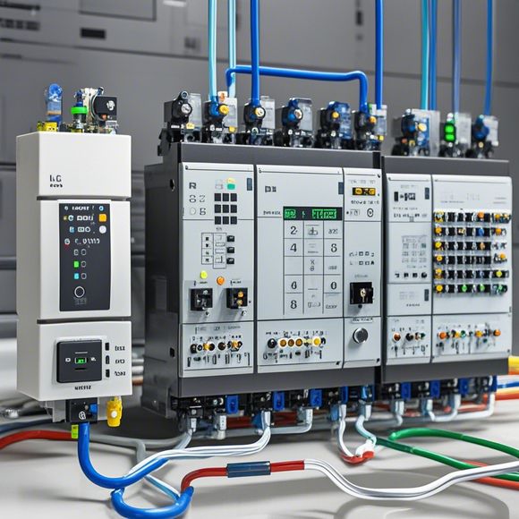
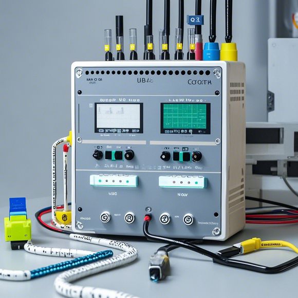
PLC Input/Output (I/O) Wiring Diagrams for Foreign Trade Operation
Sure! Based on your content, here's an example of a 200-300 word summary:"In foreign trade operations, the process of wiring and connecting Input/Output (I/O) devices is crucial. An PLC (Programmable Logic Controller) I/O wiring diagram serves as a visual representation of the connections between sensors, actuators, and control panels within a manufacturing environment. The diagram outlines the flow of electrical signals from various components to ensure efficient operation of the system. It also helps in troubleshooting and maintaining the system's integrity."
In the world of foreign trade, understanding how to effectively connect and manage your PLC (Programmable Logic Controller) inputs and outputs is crucial. A well-crafted plc input/output (I/O) wiring diagram serves as the foundational blueprint for ensuring seamless communication between various hardware components within a manufacturing or control environment. This diagram not only facilitates efficient troubleshooting and maintenance tasks but also contributes significantly to the overall efficiency and reliability of the system being controlled. Here's an in-depth look at what these I/O wiring diagrams entail and their importance in the realm of foreign trade.
To start off, let's first discuss the fundamentals of plc I/O wiring diagrams. These diagrams are essential tools for any professional working with PLCs. They depict the electrical connections between the various components of a PLC system, including sensors, actuators, and other control devices. The accuracy and completeness of these diagrams determine whether the PLC can function effectively and efficiently.
When it comes to foreign trade, the importance of having accurate and up-to-date I/O wiring diagrams is paramount. These diagrams serve as a reference point for determining the correct configuration of PLC systems in foreign factories and warehouses. Without them, there's a high risk of misinterpreting data, causing errors in calculations and decisions that could impact the success of a foreign trade operation. Moreover, when it comes to dealing with international partners, having a clear and detailed I/O wiring diagram helps in demonstrating our commitment to maintaining quality standards and meeting regulatory requirements.
One of the key benefits of having accurate plc I/O wiring diagrams is the improved ability to diagnose and resolve issues quickly. In foreign trade, where time is of the essence and downtime could result in significant losses, having these diagrams available means that technicians can quickly identify and address problems without delay. Additionally, having access to these diagrams enables us to make informed decisions about the design and installation of PLC systems, thereby minimizing potential risks and enhancing the overall performance of our operations.

Another advantage of plc I/O wiring diagrams is that they provide a platform for continuous improvement. By analyzing the effectiveness of our PLC systems, we can identify areas where improvements can be made. For example, if we notice that some sensors are not providing accurate readings, it might be necessary to update their specifications or relocate them closer to the source of the data. By continuously monitoring and adjusting these diagrams, we can ensure that our PLC systems continue to operate at peak performance levels, ultimately contributing to increased productivity and profitability.
Furthermore, having accurate plc I/O wiring diagrams enhances communication and collaboration among team members. When everyone understands the same set of rules and standards, it becomes easier for them to work together seamlessly. This not only speeds up the process of implementing changes but also ensures that all parties are aligned on the desired outcome.
In conclusion, plc input/output (I/O) wiring diagrams are critical tools for anyone involved in foreign trade operations. Their importance lies in their ability to ensure efficient communication, prevent errors, and improve overall performance. By consistently updating and maintaining these diagrams, we can minimize the risks associated with foreign trade operations while maximizing the potential for success. Remember, investing in these diagrams early on can save time, money, and resources later on, making foreign trade operations more streamlined and effective.
Content expansion reading:
Content:
Hey there! If you're new to the world of PLCs (Programmable Logic Controllers), one of the first things you'll need to wrap your head around is how to interpret those complex input/output wiring diagrams. Don't worry, it's not as daunting as it seems! Let's break it down in a way that's easy to understand.
First things first, what is a PLC input/output (I/O) wiring diagram? It's a blueprint that shows how the various inputs and outputs of a PLC are connected to other devices, sensors, and actuators in your industrial control system. Inputs are the signals that the PLC receives from the environment, like switches, sensors, or buttons. Outputs are the signals that the PLC sends out to control devices, such as motors, lights, or valves.
When you're looking at a PLC I/O wiring diagram, you'll typically see a grid of symbols representing the inputs and outputs. Each symbol has a specific meaning and is connected to a specific pin on the PLC. Here's a quick rundown of some common symbols you might encounter:
- Inputs: These are usually represented by a circle with a line coming out of it. The line might have a "+" or "-" sign to indicate the type of signal (e.g., positive or negative logic).
- Outputs: These are typically shown as a square or a rectangle with a line coming out of it. The line might also have a "+" or "-" sign, depending on the type of signal.
- Power Supply: This is usually represented by a battery symbol or a plus and minus sign. It indicates the voltage supply for the PLC and its components.

- Wires: The lines connecting the symbols represent the wires that physically connect the PLC to the devices. Different line styles or colors may indicate different types of wiring or functions.
To read the diagram, you follow the wires from the inputs to the PLC and from the PLC to the outputs. It's important to note that the diagram will also show you the type of signal (analog or digital) and the specific pin numbers on the PLC that each input and output is connected to.
When you're working with PLCs, it's crucial to have a clear understanding of these diagrams because they guide you on how to wire everything up correctly. Miswiring can lead to system failures, damage to equipment, or even safety hazards.
So, how do you ensure you're interpreting these diagrams correctly? Here are a few tips:
1、Familiarize yourself with the common symbols and their meanings.
2、Always refer to the manufacturer's documentation for the specific PLC model you're working with.
3、Double-check your work against the diagram to ensure all connections are correct.
4、If you're unsure about anything, consult with a more experienced colleague or refer to industry resources and forums for guidance.
Remember, practice makes perfect. The more you work with PLC I/O wiring diagrams, the more comfortable and proficient you'll become at interpreting them.
Articles related to the knowledge points of this article:
Smart Manufacturing Solutions with PLC Integrated Machinery
PLC Programming for Automation Control in the Manufacturing Industry
PLC (Programmable Logic Controller) Control System Basics
The Role of Programmable Logic Controllers (PLCs) in Foreign Trade Operations
Connecting a PLC Controller to Your Computer
PLC Controllers: A Comprehensive Guide to Understanding Their Prices