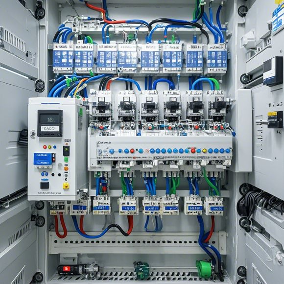
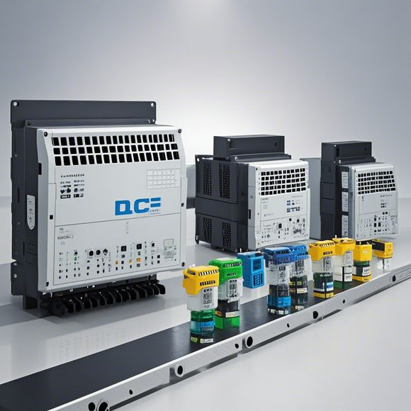
PLC Input and Output Wiring Diagram
Here is a simplified summary in English for the "PLC Input and Output Wiring Diagram":This PLC (Programmable Logic Controller) input and output wiring diagram illustrates how the various inputs and outputs are connected to the controller. The diagram shows connections from sensors, motors, and other devices to the control panel. It also indicates how data from the sensors and inputs is processed by the controller before being sent out as an output signal. The layout of the wiring diagram includes detailed drawings of wires, connectors, and components, which are essential for understanding the workings of the system.
Introduction:
Welcome to our workshop on understanding the intricacies of PLC (Programmable Logic Controller) input and output wiring. As you embark on this journey, allow me to enlighten you with some fundamental concepts that will guide you through this complex process.
The Importance of PLCs:
Before we dive into the technicalities, it's crucial to understand the significance of Programmable Logic Controllers (PLCs) in modern industrial automation. PLCs are intelligent devices that can execute a series of instructions based on inputs from various sensors or actuators. They play a vital role in controlling systems, manufacturing processes, and ensuring smooth operation across various industries.

What is PLC Input:
PLC inputs refer to the various physical signals that are received by the PLC. These signals can be analog or digital, and their purpose varies depending on the application. For example, an analog input might be a temperature sensor reading, while a digital input could represent a button press. The quality of these inputs directly affects the accuracy and reliability of the overall system.
What is PLC Output:
PLC outputs are the actions that PLCs take as a result of receiving input signals. They range from simple actuations like turning on/off lights or motors, to more complex tasks such as controlling valves or adjusting pressure levels. The type of output depends on the needs of the specific application, and its functionality is crucial for ensuring efficient and safe operation.
Wiring Diagram Basics:
Now let's delve into the world of wiring diagrams. A wiring diagram is a visual representation of how electrical components are interconnected within an electronic system. It helps to clarify the flow of power and signals between different parts of the system. In the context of PLCs, a good wiring diagram should clearly define the connections between the PLC, its input devices, and output components.
Components and Connectors:
Let's start by identifying some of the key components involved in a typical PLC input and output setup. The PLC itself serves as the brain of the system, processing data and making decisions based on inputs. Its input modules receive signals from various sensors or actuators, while its output modules send commands to external devices.
Connectors are essential components that connect different wires together. They ensure that the power and signals flow smoothly from one component to another. Common connectors used in PLCs include plugs, sockets, and screw terminals, among others.
Wire Harnesses:
Wire harnesses are another crucial aspect of PLC wiring. They bundle multiple wires together to prevent short circuits and provide a neat, organized way to route the wiring. The choice of wire gauge and type depends on the voltage and current requirements of the system.
Power Supplies:
Power supplies are responsible for providing the necessary voltage and current needed by the PLC and other components. They come in various forms, including direct-current (DC) supplies or alternating-current (AC) supplies, and they may also incorporate filters to reduce noise and interference.
Sensors and Actuators:
Sensors detect physical changes or parameters that require monitoring, while actuators respond to those sensor inputs and perform specific actions. Some common sensors used with PLCs include temperature sensors, proximity sensors, and motion sensors, while actuators can range from motors and pumps to valves and switches.
Control Systems:
Control systems are the backbone of any production line or industrial setting. They manage the sequence of events and coordinate the activities of different components to achieve optimal performance. PLCs play a critical role in implementing these control strategies, ensuring that systems remain reliable, efficient, and safe.
Maintenance and Troubleshooting:

Regular maintenance is essential for ensuring the longevity of PLC systems. This includes checking for loose connections, verifying power supply stability, and inspecting for signs of damage or wear. In the event of issues, troubleshooting can involve identifying the source of the problem and implementing corrective measures to fix the issue.
Conclusion:
In conclusion, understanding PLC input and output wiring is crucial for anyone working with automation systems. From selecting appropriate connectors and wires to managing control systems, there's much to learn. By following these steps and keeping an eye on your PLC's input and output connections, you can ensure that your systems operate efficiently and safely. Remember, a well-maintained PLC is a valuable asset that can transform your operations and improve productivity.
Content expansion reading:
Content:
Hey there! If you're new to the world of PLCs (Programmable Logic Controllers), one of the first things you'll need to wrap your head around is how to interpret those complex input and output wiring diagrams. Don't worry, though—it's not as intimidating as it seems! Let's break it down in a way that's easy to understand.
First things first, what is a PLC? It's a type of industrial computer that's designed to control and automate various machines and processes. The heart of a PLC is its I/O (Input/Output) system, which is what we're going to focus on today.
An I/O wiring diagram is a blueprint that shows how the PLC is connected to the devices it controls or monitors. These diagrams are essential for troubleshooting, maintenance, and understanding how your system works.
Let's start with inputs. These are the parts of the system that provide data to the PLC. Think of them as the eyes of the PLC—they let it "see" what's going on in the real world. Common input devices include switches, sensors, and transducers.
On the diagram, you'll see symbols for these devices. For example, a switch might be represented by a simple line with a circle on the end, while a sensor could have a more complex shape. The lines coming out of these symbols show how they're connected to the PLC.
Now, outputs are where the PLC sends signals to control other devices. They're like the hands of the PLC, telling other parts of the system what to do. Outputs can be relays, solenoids, or even motors.
In the diagram, outputs are shown with symbols that reflect their function. A relay might be a simple rectangle with a coil and contacts, while a motor might be a more detailed symbol with a shaft and pulley. The lines leaving the PLC and connecting to these devices show the output paths.
One key thing to look for in an I/O diagram is the addressing. Each input and output is given a unique address so the PLC can identify it. This is usually a number or a letter/number combination. Make sure you understand the addressing scheme for your specific PLC model.
Another important aspect is the type of signal being transmitted. PLCs can handle different types of signals, like digital (on/off) or analog (varying voltage or current). The diagram will indicate the type of signal and the corresponding wiring.
When you're looking at an I/O diagram, it's also crucial to understand the function of each component. For instance, a normally open switch will trigger an input when it's open, while a normally closed switch will do the opposite.
In summary, PLC input and output wiring diagrams can seem complex at first, but they're just a way to visually represent the connections between the PLC and the devices it controls. By understanding the symbols, addressing, and signal types, you'll be able to read these diagrams like a pro. Remember, practice makes perfect!
Articles related to the knowledge points of this article:
PLC Controller Selection Guide for Foreign Trade Operations
Mastering the Art of Plc Controllers: A Comprehensive Guide to Understand and Implement
The cost of a PLC Controller: A Comprehensive Analysis
PLC Programming for Automation Control in the Manufacturing Industry