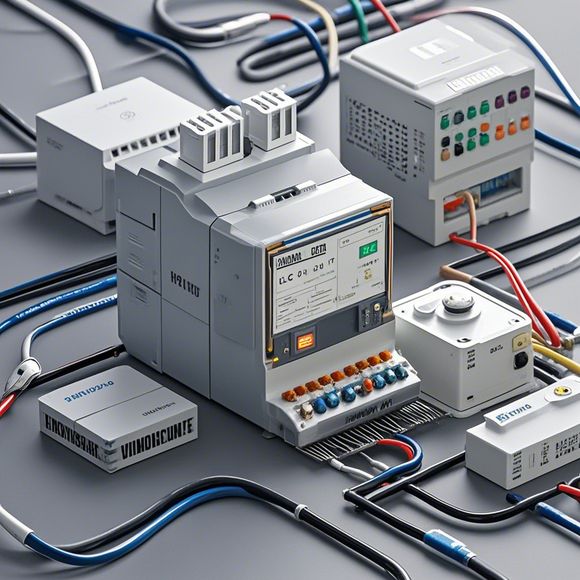
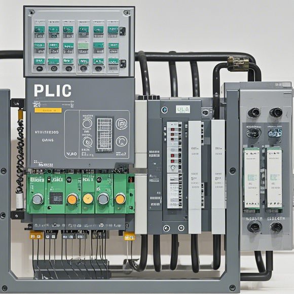
Plc (Programmable Logic Controller) System Overview
Sure, here's a brief overview of the Programmable Logic Controller (PLC) system:The PLC is a computerized control device used in manufacturing and industrial settings to monitor and manage processes. It's designed to be versatile, allowing for easy integration with various sensors, actuators, and software systems. The PLC operates by receiving commands from its programmable input/output modules, processing them, and then sending output signals to control devices. These devices can range from simple relays to complex microprocessor-based systems. The PLC can also communicate with other computers or networks through standard communication protocols like RS-232, USB, or Ethernet. This allows for greater automation and flexibility in industrial applications. Overall, the PLC is a critical component in modern manufacturing and production processes, enabling efficient and reliable operation of complex systems.
In the world of manufacturing and automation, the PLC (Programmable Logic Controller) system stands as a beacon of precision and efficiency. At the heart of this sophisticated control system lies the ability to program logic functions that can automate complex operations, making it ideal for industrial settings ranging from small-scale workshops to large-scale factories. The PLC system's core is built on the foundation of digital electronics, which enables it to process vast amounts of data at lightning speeds and make precise decisions based on inputs from sensors, actuators, or other input devices. This combination of technology and functionality has made the PLC system an indispensable tool across various industries, allowing them to achieve higher levels of productivity, reliability, and safety. In this guide, we will delve into the principles behind the PLC system, its components, and how it operates in real-world scenarios. By understanding these fundamental concepts, you will be better equipped to navigate the complexities of PLC programming and implementation, ultimately leading to more streamlined and cost-effective production processes. So let's start by exploring the basics and how the PLC system works in action.

Content expansion reading:
Content:
Hey there! If you're new to the world of PLCs (Programmable Logic Controllers), or you're looking to brush up on your knowledge, understanding PLC control system wiring diagrams is a crucial step. These diagrams are the blueprint that tells you how all the components of a PLC system are connected and how they work together. In this post, we're going to dive in and break down what you need to know to make sense of these diagrams.
First things first, let's talk about what a PLC actually does. A PLC is a type of industrial computer designed to control and automate various electromechanical processes. It's like the brain of a machine, receiving input from sensors and switches, processing that information according to pre-programmed instructions, and then outputting control signals to actuators and other devices.
Now, let's get into the nitty-gritty of those wiring diagrams. A typical PLC control system wiring diagram will show you the following:
1、Power Supply: This is the source of electrical power for the PLC. It's usually a 24-volt DC supply, but can also be AC depending on the system.
2、PLC Unit: This is the heart of the system. It's where the logic and decision-making happen. The diagram will show the input and output modules connected to the PLC.
3、Input Devices: These are the sensors, switches, and other devices that provide data to the PLC. They're usually connected to the input modules.
4、Output Devices: These are the actuators, motors, and other devices that the PLC controls. They're connected to the output modules.
5、Relay Logic: If the system has relays, the diagram will show how they're connected to the PLC and other devices. Relays are like electrical switches that can control higher voltage or current devices.
6、Control Panel: This is the user interface where you can monitor the system and make adjustments. It might include buttons, switches, and a display.
7、Wiring: The diagram will show the actual wiring between all the components, including the wire type and length if specified.

When you're looking at a PLC control system wiring diagram, it's important to pay attention to the symbols used. Each component has a specific symbol, and the wiring is represented by lines with arrows that indicate the direction of the electrical signal.
Here's a quick rundown of some common symbols you might see:
Power Supply: A rectangle with "+" and "-" signs indicating the positive and negative terminals.
PLC: A square or rectangle with multiple terminals indicating the inputs and outputs.
Input Devices: Symbols like switches or sensors with arrows showing the flow of the input signal.
Output Devices: Symbols for motors, lights, or other devices with arrows indicating the flow of the output signal.
Relay: A coil and two or more contacts that open and close to control the flow of electricity.
Remember, the key to understanding these diagrams is to look for the flow of information and power. Inputs flow into the PLC, the PLC processes the information, and then outputs flow out to control the system.
If you're new to PLCs, don't be intimidated by the complexity of these diagrams. They can seem overwhelming at first, but with a bit of practice and a good understanding of the basic components, you'll be able to read and interpret them with ease.
Always refer to the manufacturer's manual or documentation for your specific PLC system, as each one can have slightly different components and wiring configurations. And if you're ever in doubt, don't hesitate to reach out to a more experienced colleague or professional for help.
So there you have it, a quick guide to understanding PLC control system wiring diagrams. Keep practicing, and soon you'll be able to interpret them like a pro!
Articles related to the knowledge points of this article:
PLC Controller Selection Guide for Foreign Trade Operations
Mastering the Art of Plc Controllers: A Comprehensive Guide to Understand and Implement
The cost of a PLC Controller: A Comprehensive Analysis
Plumbers Rule! The Role of PLC Controllers in the World of Waterworks
Connecting a PLC Controller to Your Computer
PLC Controllers: A Comprehensive Guide to Understanding Their Prices