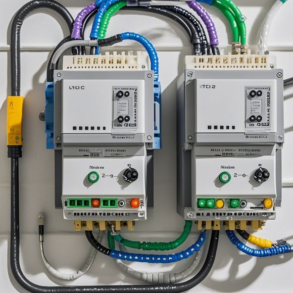
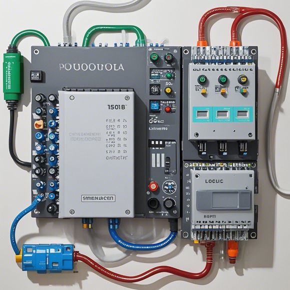
PLC Controller Wiring Diagrams and Interpretation for Beginners
Introducing PLC (Programmable Logic Controller) Controller Wiring Diagrams and Interpretation for Beginners!Firstly, let's talk about what a PLC is. PLC stands for Programmable Logic Controller, which is a type of electronic device designed to control and manage the flow of electrical signals in industrial settings. It's like an intelligent computer that can run complex programs to control various machines and equipment.Now, onto wiring diagrams. A wiring diagram is a visual representation of how different wires connect together in a circuit. It shows where each wire goes, what it's connected to, and how it affects other components. In the context of PLC controllers, these diagrams are crucial for understanding how the controller communicates with its surrounding hardware.So, how do we interpret these diagrams? Well, it depends on the complexity of the system being controlled. For beginners, I recommend starting with simpler systems and gradually moving up to more complex ones. Once you have a good grasp of basic principles, you can start looking at more advanced wiring diagrams and their interpretation.In summary, PLC controller wiring diagrams and interpretation are important tools for anyone working with industrial automation systems. By understanding these diagrams, you can ensure your PLC controller is functioning correctly and efficiently controlling the devices it controls.
Hello everyone, today I am going to share with you some basic understanding of how to read a plc (programmable logic controller) controller wiring diagram. As an experienced trader, it's crucial that you understand the basics before diving into complex projects. So here we go!
Firstly, let me give you a brief overview of a typical plc controller wiring diagram. A wiring diagram is a visual representation of how electrical components are connected in a system. The key elements include input/output ports, sensors, switches, relays, motors, etc. Each device and connection has its own pin number or label that corresponds to the circuit board on which it is located.
Now, let me walk you through the basic steps of reading a plc controller wiring diagram:

1、Understanding the Circuit Board: Before you start looking at the wiring diagram, it's important to familiarize yourself with the layout of the circuit board. You should be able to locate each component by its pin number or color coding. For example, motors are generally labeled with M for Motor, and so on.
2、Identifying the Devices: Once you have a sense of the layout, you can start identifying the different devices present in the circuit. This might involve looking for specific labels like "Analog Input," "Digital Output," "Pulse-Width Modulator," or "Sensor."
3、Reading Pin Numbers: Each device has a unique pin number or label that corresponds to its position on the circuit board. For instance, if there's a digital output device labeled "D0," you know that its pin number is D0. Similarly, if there's a sensor labeled "S1," you know that its pin number is S1.
4、Connecting the Devices: Once you've identified all the devices and pin numbers, you can begin connecting them together. This involves following the wiring diagram step by step, ensuring that all connections are correct and secure.
5、Practice Makes Perfect: The more you work with wiring diagrams, the more familiar you'll become with them. Don't be afraid to make mistakes – practice makes perfect!
6、Documentation and Maintenance: After completing your project, it's essential to document the wiring diagram so that future maintenance or upgrades can be easily done without any confusion.
In conclusion, understanding how to read a plc controller wiring diagram is critical for any professional in the field. By following these simple steps, you'll be well on your way to becoming a proficient engineer. Remember, patience is key – don't get discouraged if you make a mistake – keep practicing and you'll get it!
Content expansion reading:
Content:
Hey there! If you're new to the world of PLCs (Programmable Logic Controllers), or you just need a refresher on how to read those complex wiring diagrams, you've come to the right place. PLCs are the brains of many industrial control systems, and being able to interpret their wiring diagrams is crucial for any electrical technician or engineer. Let's dive in and demystify those diagrams together!
First things first, a PLC controller wiring diagram is a blueprint that shows how all the electrical components in a PLC system are interconnected. It's like a map that tells you where everything is and how it's connected. The diagram typically includes power supplies, PLC racks, input/output modules, and any other peripherals like sensors, motors, and switches.
Now, let's break down the key elements of a PLC controller wiring diagram:

1、Power Supply: This is where the magic starts. The power supply provides the electrical power to the PLC system. It's usually a DC supply, but some systems use AC power.
2、PLC Racks: These are the frames that hold the PLC modules. Each rack has a specific number of slots where modules can be inserted.
3、PLC Modules: These are the functional parts of the PLC. Input modules receive signals from sensors or switches, while output modules control actuators or motors. There are also specialty modules for communication, timing, and counting.
4、Wires and Connectors: These are the literal lifelines of the system. They connect all the components together. Make sure you're using the right type of wire and connectors for the job.
5、Terminals: These are the points on the modules where the wires connect. They can be screw terminals, spring-clamp terminals, or more advanced connection methods.
6、Junction Boxes: These are metal or plastic enclosures that protect the wiring and connections. They're often used in industrial settings to keep everything safe and organized.
7、Sensors and Actuators: These are the devices that interact with the environment. Sensors detect changes and send signals to the PLC, while actuators receive signals from the PLC and perform an action.
When you're looking at a PLC controller wiring diagram, it's important to understand the symbols used. Each component has a specific symbol, and the wires are represented by lines with arrows that indicate the direction of the electrical signal.
Here's a quick tip: Always start at the power supply and follow the lines to each component. This will help you understand the flow of the system.
Remember, safety is paramount when working with PLCs and electrical systems. Always ensure that the power is off before you start making any connections, and use the right tools for the job.
That's it for a quick overview of PLC controller wiring diagrams. With a bit of practice, you'll be able to read these diagrams like a pro. Happy troubleshooting!
Articles related to the knowledge points of this article:
PLC Controller Wiring Guideline
PLC Programming for Automation Control in the Manufacturing Industry
PLC (Programmable Logic Controller) Control System Basics
Connecting a PLC Controller to Your Computer
PLC Controllers: A Comprehensive Guide to Understanding Their Prices