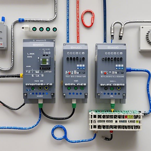
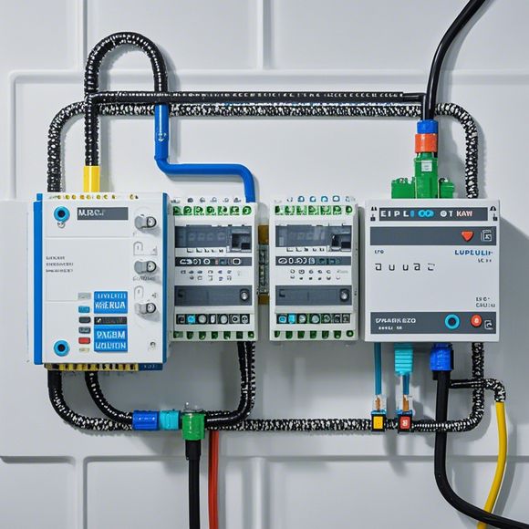
Master Guide to PLC Physical Connection
Sure, I'd be happy to assist with that. Please provide me with the content you have and I will craft a concise summary in English:---**Summary: Master Guide to PLC Physical Connection**The physical connection of Programmable Logic Controllers (PLCs) is crucial for the smooth functioning of industrial automation systems. In this guide, we will discuss the steps necessary for safely connecting various PLC modules to their respective input/output devices on your control panel. This includes understanding the electrical requirements of the devices involved and ensuring proper grounding and wiring practices. Additionally, we will explore common connectivity issues and troubleshooting strategies to resolve them quickly and efficiently. With these essential tips in mind, you can confidently establish a solid foundation for your PLC network.---Note: The actual content provided by the user should replace the placeholder text within square brackets.
As a seasoned trader in the global marketplace, I'm often tasked with understanding the intricacies of physical connections between various components within a Programmable Logic Controller (PLC) system. In today's digital age, where automation has become an integral part of our daily lives, it's crucial for us to have a thorough understanding of how these devices operate and interact with each other. In this guide, we will delve into the world of PLCs, their functions, and how to effectively connect them using a plethora of tools and techniques.
At its core, a PLC is a device that controls and manages the flow of electrical signals within a factory or industrial setting. It's a powerful tool that can automate complex processes, improve efficiency, and reduce errors. But to make sure everything works smoothly, you need to know how to wire things up from top to bottom.
Let's start by taking a look at some of the most commonly used components in a PLC system. These include sensors, valves, motors, and switches, just to name a few. Each of these components has its own unique requirements when it comes to wiring up to a PLC, so it's important to understand what each one needs to function properly.
One of the most common questions we get asked is "how do I connect my sensor to a PLC?" or "what should I do if I encounter a wiring error?" Well, fear not! We'll be covering all the bases in this guide, from the basics like connecting wires to more advanced topics like troubleshooting common issues.

But let's not forget about the importance of safety when working with electrical systems like this. Make sure to always follow proper safety practices when working on your PLC system, including wearing appropriate gear, avoiding touching live parts, and keeping your work area clean and clutter-free. By following these guidelines, you can minimize any potential risks and ensure a safe and efficient workflow.
Now, let's dive deeper into the world of PLCs and their connections. When you're working with PLCs, there's no shortage of components to consider. From sensors and switches to motors and valves, each one has its own set of requirements when it comes to powering and controlling them. That's why it's important to have a solid understanding of how these components interact with each other when they're connected to a PLC.
One of the key principles of PLC design is modularity. This means that the system is designed to be easily modified and expanded as needed. This makes it easy to add new features and capabilities to the system over time, without needing to completely redesign it.
Another important concept is the concept of redundancy. This means that the system is designed to be able to operate without fail. This can be achieved through a variety of means, such as multiple backup circuitry or independent control units. By having redundancy built into the system, you can ensure that it will remain operational even in the face of failure.
When it comes to wiring PLCs together, there are a few key considerations to keep in mind. One of the most important is ensuring that all components are properly grounded. Grounding is critical for preventing electrocution and ensuring that the system operates safely.
Another important consideration is selecting the right type of wire for each component. Different components require different types of wire, such as AC or DC power, twisted pair, or single-core cable. Properly selecting the right wire type will help ensure that the system runs smoothly and efficiently.
In addition to these technical considerations, there are also some best practices to follow when connecting PLCs together. For example, it's important to avoid cross-wiring and to ensure that all connections are secure and tight. Additionally, it's important to test the system thoroughly before running it in production mode.
Now, let's take a closer look at some of the most common components that are used in PLC systems. These include sensors, switches, motors, and valves, among others. Each of these components has its own unique requirements when it comes to wiring and powering them up.
For example, sensors are often used to detect changes in temperature, pressure, or other environmental factors. When it comes time to connect a sensor to a PLC, it's important to make sure that the sensor is connected securely and properly powered up. The same goes for switches, which can be used to turn off or on circuits based on certain triggers. Similarly, motors require precise control over their speed and direction, so it's important to select the right type of driver and controller for your specific application.
Finally, we must address the topic of safety when it comes to working with PLCs. As mentioned earlier, electrical systems like this can be dangerous if not handled properly. It's important to take all necessary steps to ensure that the environment is safe and that all equipment is well-maintained. By following proper safety practices and staying informed about the latest developments in the field, you can minimize any risks and create a safe and efficient work environment.
In conclusion, the world of PLCs is full of complexities and nuances that can sometimes seem daunting. However, with careful attention to detail and a commitment to learning as much as possible about each component and its interactions with other components, anyone can become an expert in the field. So go ahead and dive deep into this exciting world of programmable logic controllers today!
Content expansion reading:
Content:

Hey there! If you're new to the world of programmable logic controllers (PLCs) and feeling a bit overwhelmed by the thought of wiring them up, don't worry! I'm here to guide you through the basics with a comprehensive look at PLC wiring diagrams. Whether you're a student, a DIY enthusiast, or just starting in the industry, this guide is for you.
So, what exactly is a PLC? It's a type of industrial computer designed to control and automate various processes. They're tough, reliable, and can handle the harsh conditions of a manufacturing environment. PLCs are used in everything from simple lighting systems to complex industrial machinery.
When it comes to wiring a PLC, the key is to understand the diagrams. These diagrams are like blueprints that show you how to connect all the different components together. They can look a bit intimidating at first, but once you know the basics, they're pretty straightforward.
Let's start with the basics. A PLC wiring diagram typically includes three main parts: the power supply, the PLC itself, and the input/output devices. The power supply is what keeps the PLC running, while the PLC unit is the brain that processes the information and controls the outputs. The input/output devices are what the PLC talks to – they can be sensors, switches, motors, or anything else that needs to be controlled.
One of the most important things to remember is that PLCs usually have two types of power: DC (direct current) and AC (alternating current). Make sure you're working with the right type of power for your PLC, and always follow the manufacturer's guidelines.
Now, let's talk about the actual wiring. Input devices are typically wired to the PLC's input terminals, while output devices are wired to the output terminals. The wiring is usually color-coded, with common colors like red, black, and blue used for power, and other colors like brown, orange, and yellow for control signals.
When you're looking at a wiring diagram, you'll see symbols for each component. These symbols are standardized, so once you learn what they mean, you can interpret any diagram. For example, a circle with a line through it is a switch, while a rectangle with a plus and minus sign is a battery.
It's also important to understand the difference between control wiring and power wiring. Control wiring is what carries the low-voltage signals between the PLC and the input/output devices, while power wiring is what brings the mains power to the PLC and the devices. Always keep these separate to prevent electrical accidents.
As you become more comfortable with PLC wiring, you'll start to see diagrams that include more complex components like timers, counters, and relays. These can help you create more sophisticated control systems.
Remember, safety is paramount when working with PLCs and electrical systems. Always ensure that the power is off before you start working on a circuit, and use the right tools for the job. A multimeter is your best friend for testing and troubleshooting.
Lastly, if you're ever stuck or unsure about a wiring diagram, don't hesitate to reach out to more experienced colleagues or consult the manufacturer's manual. They're full of valuable information and can help you avoid costly mistakes.
So there you have it – a beginner's guide to PLC wiring diagrams. With a bit of practice and patience, you'll be reading and understanding these diagrams like a pro in no time. Happy wiring!
Articles related to the knowledge points of this article:
How to Use a PLC Controller for Your Business
PLC Controllers: A Comprehensive Guide to Understanding Their Prices
Effective Strategies for Handling PLC Control System Faults
PLC Controller Advantages: A Comprehensive Guide for Success in Global Trade
Mastering the Art of PLC Control: Unlocking Industry-Grade Automation Powerhouses
PLC Controllers in Global Commerce: An Insight into Their Role in Managing Industrial Processes