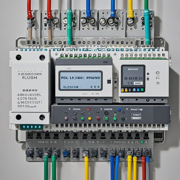
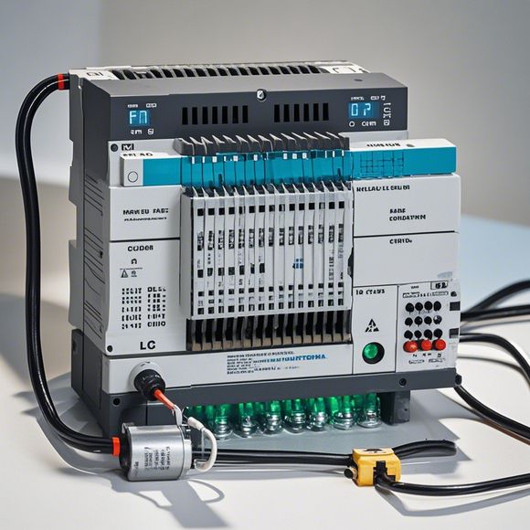
plc控制器接线图
Title: PLC Controller Wiring DiagramHello! Let's talk about the PLC controller wiring diagram. As a professional in the field, I often need to understand and operate it. The wiring diagram is an essential tool for me. It helps me quickly find where each component is located and how to connect them together.The wiring diagram is divided into two parts: the control panel and the mainframe. On the one hand, the control panel includes various input and output devices such as switches, buttons, sensors, and indicators. These components are responsible for receiving user commands and sending feedback signals to the mainframe. On the other hand, the mainframe is the core of the PLC controller, mainly composed of a CPU, memory, and power supply. The CPU is the brain of the device, responsible for processing the input signals and executing the corresponding programs. The memory is used to store programming codes, while the power supply ensures stable operation.When we design a wiring diagram, we must consider not only the physical layout but also the logical relationship between the components. For example, if there are multiple input devices, we need to ensure that they all receive the same signal at the same time. This requires careful planning and coordination. Moreover, we must also pay attention to safety issues during the wiring process. For instance, we should avoid crossing wires or using short-circuiting connections, which could cause damage or safety hazards.In addition to the physical aspects mentioned above, the design of the wiring diagram also needs to meet certain technical standards. We need to follow industry-standard electrical symbols, use appropriate voltage levels, and arrange the circuits according to their actual working conditions to ensure efficient and safe operations.In conclusion, a well-designed PLC controller wiring diagram is crucial for ensuring the reliability and efficiency of the system. By understanding its structure and principles, we can better operate and maintain the device and achieve our goals more effectively.
"PLC Controller Wiring Diagram: A Step-By-Step Guide to Understanding and Troubleshooting Your System"

Content:
Hello, everyone! Today, I want to share with you a comprehensive guide on how to wire the PLC (Programmable Logic Controller) controller for your industrial automation needs. So, if you're looking to streamline your production processes, improve efficiency, or enhance product quality, this guide will be incredibly useful for you. Let's dive right in!
Firstly, it's important to have a clear understanding of what an PLC controller is. In simple terms, it's an intelligent computer that can control various industrial systems by executing pre-programmed logic based on input data from sensors and other devices. It's like a supercomputer that can handle complex calculations and execute commands in real-time. Now, let's move on to the wiring diagram.
The PLC controller wiring diagram will give you an overview of the components that make up your system. You'll see symbols representing different types of connections, such as power supply lines, communication cables, and input/output ports. The diagram will also indicate which pins are connected to what device, making it easy for you to understand where each component comes in.
Now, let's talk about the main parts of the wiring diagram. First off, there will be the main power supply line that connects to the electrical outlet. This is the lifeblood of your system, providing the necessary energy to keep everything running smoothly. Next, you'll see communication lines connecting the controller to other devices, such as sensors, actuators, and computers. These lines allow for the exchange of data between the controller and other elements in your system. Finally, you'll see the input and output ports, which are where you connect various sensors, switches, and actuators to your PLC controller. These ports enable you to read incoming data from sensors, process it according to your program, and send out commands to actuators.

So, now that we've discussed the basics of the wiring diagram, let's take a closer look at some common issues that might arise during installation. One potential problem is incorrect wiring. If you don't follow the diagram carefully and connect the wrong wires or terminals, it could result in errors during operation. For example, if you use the wrong color code for your wiring, it may cause confusion when troubleshooting. Another issue is improper installation, such as not securing cables properly or not following the recommended distance between components. This can lead to electromagnetic interference or reduced performance. Finally, you should always ensure that all connections are securely made and free from any damage or wear. By following these steps, you can help prevent common problems and ensure a smooth and reliable PLC controller setup.
In summary, understanding the PLC controller wiring diagram is crucial for any industrial automation project. With this guide, you'll be able to confidently connect the various components and address any potential issues that may arise. Remember to consult the diagram carefully and follow the instructions provided. By doing so, you'll be setting yourself up for success and ensuring that your PLC controller is working efficiently and reliably.
Content expansion reading:
Articles related to the knowledge points of this article:
PLC Controller Selection Guide for Foreign Trade Operations
Mastering the Art of Plc Controllers: A Comprehensive Guide to Understand and Implement
PLC Controller Wiring Guideline