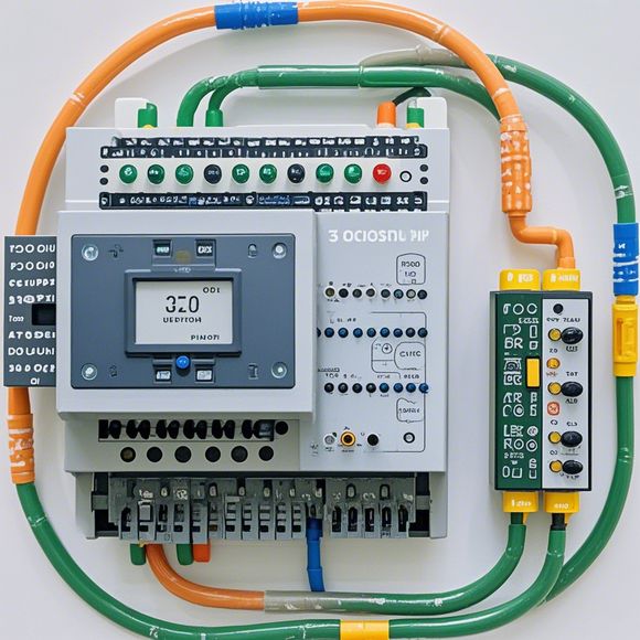
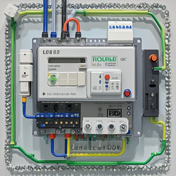
PLC Input/Output Wiring Diagram for Your Trade Operations
Here's a brief summary in English, tailored to your needs:"In order to ensure efficient and effective trading operations, you should consider PLC input/output wiring diagrams. These diagrams provide detailed instructions on how to connect various components such as sensors, actuators, switches, and relays to the control panels of your equipment. With this knowledge, you can easily troubleshoot any issues that may arise during operation and make informed decisions based on real-time data. Additionally, it's important to regularly review and update these diagrams to reflect changes in hardware or software configurations. This will help ensure that your systems remain secure and up-to-date."Note: The provided text is a general summary of what you asked for, but without specific content details or context, it's difficult to tailor the summary more closely to your needs. If you have more information on which specific elements you want to emphasize or if there are any particular aspects you wish to highlight, please let me know so I can provide a more tailored summary.
Hello, dear colleagues! Today I'm thrilled to share with you the essential information about our company's production process, specifically the PLC (Programmable Logic Controller) input and output wiring diagram. As a seasoned trader, this is something that we take very seriously, as any glitch in the system can lead to delays or even complete failure of the operation.
The PLC, or Programmable Logic Controller, is an integral part of our manufacturing process, which ensures smooth operations without human intervention. It's a marvel of modern technology that allows us to automate various functions, from feeding machines to sorting products, all thanks to its advanced programming capabilities.
Now, let's talk about the input and output wiring diagram. This is where the magic happens. The PLC takes inputs from various sources such as sensors, actuators, and other devices, interprets them, and then sends out commands to perform specific tasks. The outputs are used to control the movement of machinery, lights, and other systems.
So, how does it work? Well, the input wiring diagram shows the various components that feed data into the PLC, like sensors or switches. The output wiring diagram illustrates how these inputs are transformed into actual actions by the PLC. It's like a blueprint for our production floor, showing us exactly where everything is located and how it all connects together.

But don't worry if at first glance it all seems a bit too technical. We're here to make it easy for you. So, let me break it down for you. First, there's the main panel, which houses the PLC and serves as the brain of the entire system. Then comes the sensors, which detect conditions like temperature or pressure and relay that information to the PLC. Actuators follow up on those signals, moving things like conveyor belts or valves accordingly. And don't forget about the displays - they give us real-time insights into how everything is working, helping us troubleshoot issues quickly.
Now, let's get back to the point. Our input/output wiring diagram is a treasure trove of knowledge that helps us keep our factory humming along smoothly. From the intricate connections between sensors and actuators to the complex interactions between different systems, every detail plays a crucial role in ensuring that we produce quality products on time and within budget.
And don't worry if at first glance it all seems a bit too technical. We're here to make it easy for you. So, let me break it down for you. First, there's the main panel, which houses the PLC and serves as the brain of the entire system. Then comes the sensors, which detect conditions like temperature or pressure and relay that information to the PLC. Actuators follow up on those signals, moving things like conveyor belts or valves accordingly. And don't forget about the displays - they give us real-time insights into how everything is working, helping us troubleshoot issues quickly.
Now, let's dive right into the details. Our input/output wiring diagram is a detailed representation of how our factory operates. It's like a map of our production floor, showing us exactly where everything is located and how it all connects together. Each component has its own unique set of wires and connectors, each designed to work together seamlessly to achieve optimal performance.
From the main panel to the sensors, from the actuators to the displays, every component plays a critical role in ensuring that we produce high-quality products on time and within budget. And don't worry if at first glance it all seems a bit too technical. We're here to make it easy for you. So, let me break it down for you. First, there's the main panel, which houses the PLC and serves as the brain of the entire system. Then comes the sensors, which detect conditions like temperature or pressure and relay that information to the PLC. Actuators follow up on those signals, moving things like conveyor belts or valves accordingly. And don't forget about the displays - they give us real-time insights into how everything is working, helping us troubleshoot issues quickly.
In addition to providing a detailed overview of our factory's operations, our input/output wiring diagram also highlights some important considerations when it comes to safety and reliability. For example, we ensure that all wires are properly insulated and grounded to prevent electrical hazards and protect against electrostatic discharges. Additionally, we have strict guidelines in place for maintenance and testing procedures to ensure that our equipment stays in top shape and performs reliably.
So, whether you're a seasoned trader looking to streamline your operations or a newcomer just starting out, rest assured that our input/output wiring diagram is your best friend. With its clear layout and detailed explanations, it'll help you navigate through the complex world of industrial automation with ease. And if you ever encounter any snags or challenges along the way, don't hesitate to reach out to our team of experts who will be more than happy to lend a helping hand.
In conclusion, our input/output wiring diagram is not just a document but a living breathing entity that guides our factory's operations like no other. With its intricate details and comprehensive explanations, it provides a roadmap that leads us towards success and efficiency. So why wait? Let's embrace this valuable tool and make the most of our industrial future today!
Content expansion reading:
Content:
Hey there! If you're new to the world of PLCs (Programmable Logic Controllers), or you're looking to brush up on your knowledge, understanding input and output wiring diagrams is a crucial step. PLCs are the brains of many industrial control systems, and being able to interpret their wiring diagrams is essential for proper installation and maintenance. Let's dive in and break down what these diagrams mean in plain English.
First things first, what is a PLC input? This refers to the points at which the PLC receives signals from sensors, switches, or any other devices that are monitoring a process. Inputs can be either digital or analog. Digital inputs are binary, meaning they're either on or off, while analog inputs can vary in value, like temperature or pressure readings.

On the other side of the coin, PLC outputs are the points where the PLC sends signals to actuators, motors, or other devices to control the process. Just like inputs, outputs can be digital or analog. Digital outputs are used to turn devices on or off, while analog outputs provide a continuous signal to control the speed of a motor, for example.
Now, let's talk about wiring diagrams. These diagrams are like the blueprints for how your PLC is connected to all the other components in your system. They show the relationship between the PLC's terminals and the devices they're controlling or monitoring. Here's what you need to look for when you're staring at one of these diagrams:
1、PLC Inputs: You'll see a list of input points, often labeled with numbers or letters. Each input will have a specific type (like digital or analog) and may have additional information about the type of signal it expects.
2、PLC Outputs: Just like inputs, outputs will be listed with their corresponding numbers or letters. The diagram will indicate whether each output is digital or analog.
3、Devices: The diagram will show how the inputs and outputs are connected to the various devices in your system. This is where you'll see the wiring details, like which input corresponds to which sensor and which output goes to which actuator.
4、Power Supplies: Don't forget about the power! The wiring diagram will show how the PLC and the devices it controls are powered. This includes both the mains power input to the PLC and any DC power supplies for the devices.
5、Grounding: Proper grounding is essential for safety and to prevent electrical noise. The diagram will show how the PLC and devices are grounded.
6、Safety Features: If your system has any safety features like emergency stop buttons or interlocks, these will be clearly marked on the diagram.
When you're working with a PLC wiring diagram, it's important to pay attention to the symbols used. Different symbols represent different types of inputs, outputs, and devices. Make sure you understand what each symbol means so you can accurately interpret the diagram.
Remember, safety is paramount when working with PLCs and electrical systems. Always follow proper lockout/tagout procedures when working on live systems, and never assume a circuit is de-energized without verifying it yourself.
By understanding PLC input and output wiring diagrams, you're well on your way to becoming a pro in the world of industrial automation. Keep practicing, ask questions when you're unsure, and always prioritize safety. Happy wiring!
Articles related to the knowledge points of this article:
PLC Controller for Manufacturing Automation
How to Use a PLC Controller for Your Business
The Role of Programmable Logic Controllers (PLCs) in Foreign Trade Operations