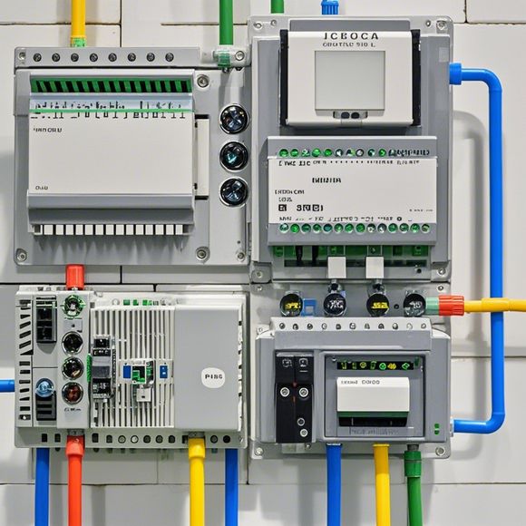
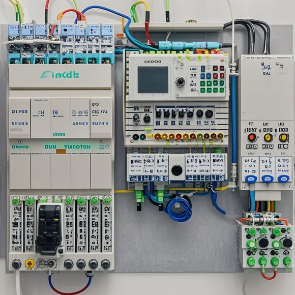
PLC Module wiring diagram
A PLC (Programmable Logic Controller) module is a crucial part of many industrial automation systems. It allows for the creation of complex control logic and processes, such as manufacturing lines or industrial robotics, through the use of digital signals to manage and control physical devices. In this context, a wiring diagram represents how these components are interconnected in an electronic circuit. Here's a quick summary of what it might look like:The PLC module contains several key elements:,1. Central Processing Unit (CPU): This is where all the logic and calculations occur, interpreting inputs from sensors and outputting commands to actuators.,2. Input/Output (I/O) ports: These connect to external devices, allowing data to be inputted or processed by the PLC.,3. Memory: Storage for instructions and configuration settings.,4. Power supply: Ensures the correct voltage and current are supplied to the various components inside the PLC module. In summary, a PLC module is an essential piece of hardware used in industrial automation, providing a foundation for complex control systems. Its wiring diagram details how different components within the module interact to achieve specific tasks.
As an experienced foreign trade operator, understanding the intricacies of PLC (Programmable Logic Controller) module wiring is crucial for ensuring smooth and efficient operations. Here's a detailed breakdown of how to navigate through the PLC module's wiring diagram using English:
1、Identify the main components of the PLC module: The PLC module typically includes a CPU, input/output modules (I/O), and various connectors for connecting various devices. Determine which components are most important based on your needs and the tasks you want to automate.

2、Analyze the wiring diagram: A typical PLC module wiring diagram will have several components labeled with their respective functions. For instance, "A" may represent the power supply, "B" could be the CPU, "C" might be the I/O modules, and so forth. Each component should be clearly labeled with its purpose to ensure proper connections.
3、Read the labeling on each wire: Each wire should be labeled with a specific color or number, indicating its function and where it connects to the other components. Pay attention to the color-coding system used, as it helps in distinguishing between different wires.
4、Connect the wires correctly: Once you understand the wiring diagram, you can start connecting the wires according to the labeling. Ensure that each wire is securely connected to its corresponding component, following the manufacturer's guidelines. If unsure about a particular connection, consult the manual or seek assistance from a professional engineer.
5、Test the circuitry: Before finalizing the wiring, test the entire circuitry to make sure it works properly. This includes testing the output signals and verifying that all components are connected correctly. If there are any issues during testing, identify them and make adjustments accordingly.
6、Maintenance and updates: Once the circuitry is complete, ensure that it remains functional by regularly monitoring and maintaining it. Keep up-to-date with software updates and firmware upgrades to ensure that the PLC module continues to perform efficiently.
By following these steps, you can navigate through the PLC module's wiring diagram in English while ensuring that your operations run smoothly and efficiently. Remember to stay informed about changes in technology and seek guidance from experts when necessary.
Content expansion reading:
Content:
Hey there! If you're new to the world of PLCs (Programmable Logic Controllers), or you're looking to brush up on your knowledge, understanding PLC module wiring diagrams is a crucial step. These diagrams can seem intimidating at first, but once you know what to look for, they're actually pretty straightforward. Let's dive in and break it down together!
PLC modules are the building blocks of a PLC system. They perform specific functions, like controlling motors, monitoring temperatures, or managing input and output signals. When these modules need to communicate with each other or with other devices, they do so through a wiring diagram. This diagram is like a blueprint that tells you how to connect the modules together.

The first thing you'll notice on a PLC module wiring diagram is a list of symbols. These symbols represent the different types of connections you'll see in the diagram. For example, you might have symbols for input and output terminals, power supplies, and more. Each symbol has a specific meaning, so it's important to understand what they represent.
Next, you'll see a grid of terminals with numbers and letters. These correspond to the physical connections on the PLC module. The numbers represent the specific terminal, while the letters often indicate the type of signal (like I for input or O for output). The diagram will show you which terminals need to be connected to each other.
One of the most common types of diagrams you'll see is the ladder diagram. This is where the "logic" in PLCs comes into play. Ladder diagrams consist of two vertical rails, with "rungs" (lines) connecting them. These rungs represent the logic that the PLC uses to control the process. Each rung is a set of conditions that, when met, will cause an output to occur.
When you're looking at a PLC module wiring diagram, it's important to follow the flow from top to bottom. Each rung is evaluated in sequence, and if the conditions are met, the output will be activated. This is why it's crucial to understand the symbols and how they interact with each other.
Now, let's talk about some practical tips for working with PLC module wiring diagrams. First, always refer to the manufacturer's documentation for the specific PLC you're working with. They will have detailed information on the meaning of each symbol and how to interpret the diagrams.
Second, use a multimeter to test your connections as you go. This will help ensure that you've wired everything correctly and that there are no loose connections or shorts. Safety first!
Lastly, take your time and double-check your work. PLCs are used in a wide range of industrial applications, from simple automation to complex control systems. A mistake in the wiring could lead to system failure or, in some cases, pose a safety hazard.
In conclusion, understanding PLC module wiring diagrams is essential for anyone working with PLCs. By familiarizing yourself with the symbols and the structure of the diagrams, you'll be able to interpret them with ease. Remember to use the resources provided by the manufacturer, test your connections, and always double-check your work. With a bit of practice, you'll be a pro at deciphering these diagrams in no time!
Articles related to the knowledge points of this article:
PLC Controller Selection Guide for Foreign Trade Operations
The cost of a PLC Controller: A Comprehensive Analysis
PLC Programming for Automation Control in the Manufacturing Industry
How to Use a PLC Controller for Your Business