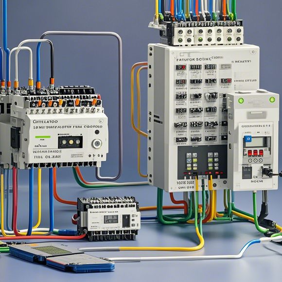
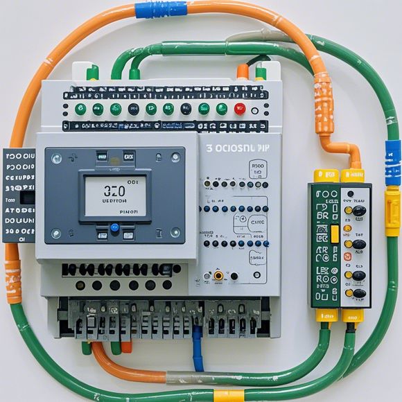
plc控制器接线图
The PLC controller wiring diagram is a visual representation of the electrical connections between the PLC and the various components within the control system. This diagram serves as an essential tool for understanding how the PLC controls various devices, including sensors, actuators, and other equipment.When drawing the wiring diagram, one should consider the input and output requirements for each device being controlled, such as motors or sensors. For example, in controlling a motor, one might have a sequence of starting and stopping, which requires I/O allocation to properly assign inputs to control the start and stop signals, and outputs to control the motor's status.Moreover, it's important to note that the layout of the wires on a wiring diagram should be logical and consistent, with all connections clearly labeled and easy to follow. The use of schematic symbols and diagrams can help simplify the process of understanding the circuitry and making any necessary adjustments or modifications.In summary, understanding the purpose and functionality of each component in the PLC control system is crucial for creating effective wiring diagrams. By carefully planning and implementing these connections, you can ensure that the PLC operates efficiently and reliably, meeting the needs of your industrial automation needs.
"PLC Controller Wiring Diagram for Foreign Trade Operations"

Introductory Paragraph:
Hello everyone, today I'm thrilled to present you with a comprehensive guide on how to wire the PLC controller for your foreign trade operations. This is an indispensable resource for anyone involved in international business, as it will assist you in ensuring smooth and efficient operations of your manufacturing or logistics systems.
The PLC (Programmable Logic Controller) is a key component in modern industrial automation, offering high-speed processing capabilities and flexibility that are ideal for handling complex tasks such as inventory management, production scheduling, and quality control. In this guide, we'll cover everything from the basics of PLC programming to the specifics of wiring your system to ensure seamless connectivity between various devices and processes.
Whether you're a seasoned professional or just starting out in the world of foreign trade, this guide is designed to provide you with the knowledge and tools you need to take your operations to the next level. So let's dive into the details and get started on your PLC controller wiring journey!
Content expansion reading:
Content:
Hey there! If you're new to the world of PLCs (Programmable Logic Controllers), or you're just looking to brush up on your knowledge, understanding PLC controller wiring diagrams is a crucial step. These diagrams can seem intimidating at first, but once you know what to look for, they're actually pretty straightforward.
So, let's dive in and break down what a PLC controller wiring diagram is and how to interpret it.
First things first, a PLC controller wiring diagram is a visual representation of the electrical connections between the various components of a PLC system. It shows you how the PLC is connected to input devices (like sensors), output devices (like actuators), and other peripheral equipment. The diagram is designed to help you understand the flow of information and power within the system.
When you're looking at a PLC controller wiring diagram, you'll typically see a few key elements:
1、PLC Module: This is the heart of the system. It's where the programming and logic take place.
2、Input Devices: These are the things that provide data to the PLC, like limit switches, sensors, or push buttons.

3、Output Devices: These are the things that the PLC controls, like motors, lights, or solenoids.
4、Power Supplies: These provide the necessary voltage to the PLC and other components.
5、Relay Contacts: These are used to control higher current loads.
6、Wires: These connect all the components together.
Each component is represented by a symbol, and the wires are represented by lines with arrows that indicate the direction of the electrical signal. The wires are usually color-coded to help with identification.
Here's a simple example of what a PLC controller wiring diagram might look like:
PLC Module
|
v
Input Devices (e.g., Sensors)
|
v
Output Devices (e.g., Actuators)
|
v
Power Supply
In this diagram, the PLC module is connected to input devices and output devices through wires. The power supply provides power to the PLC and the output devices.
When interpreting a wiring diagram, it's important to follow the flow of the diagram from left to right. Start at the power supply and work your way through the inputs and outputs, making sure you understand how each component is connected.
If you're ever unsure about a particular symbol or connection, don't hesitate to consult the manufacturer's documentation or reach out to a more experienced colleague. Safety is paramount when working with electrical systems, so always double-check your work and ensure you understand the implications of any changes you make.
Remember, practice makes perfect. The more wiring diagrams you look at and interpret, the more comfortable you'll become with them. Soon enough, you'll be reading them like a pro!
Articles related to the knowledge points of this article:
PLC Controller Selection Guide for Foreign Trade Operations
Mastering the Art of Plc Controllers: A Comprehensive Guide to Understand and Implement
PLC Controller for Manufacturing Automation
PLC Programming for Automation Control in the Manufacturing Industry