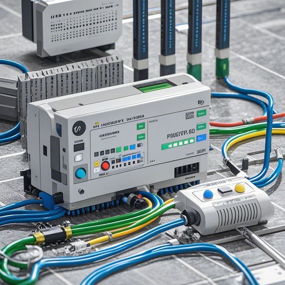
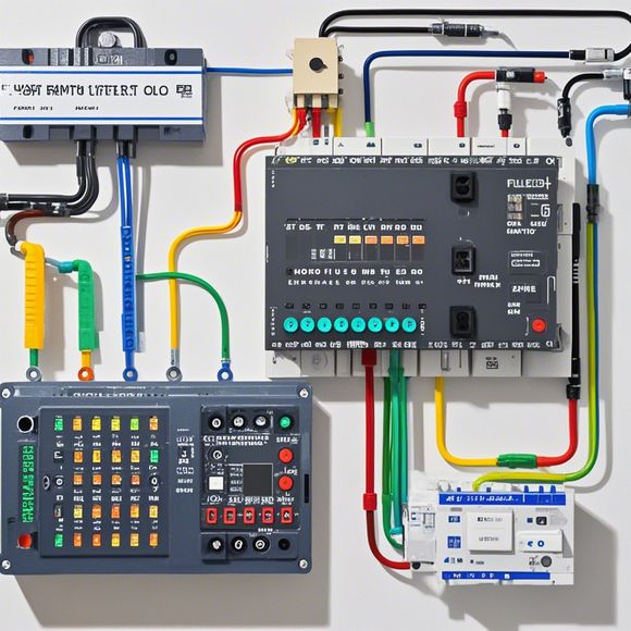
Introduction to PLC Controller Wiring Diagrams
Sure, here's a summary in English:PLC (Programmable Logic Controller) controllers are crucial in industrial automation processes. Wiring diagrams are essential for understanding how these systems function. They show the connections between different components such as sensors, actuators, and processors, which are crucial for control and monitoring.In this discussion, we will explore the basics of PLC controller wiring diagrams. The first step is to understand what a wiring diagram is. A wiring diagram is a visual representation of the electrical connections between components in a system. It shows the wires and their terminals, indicating the direction of current flow, and the purpose of each connection.The next step involves learning about different types of wiring diagrams. These include schematic diagrams, functional block diagrams, and flowchart diagrams. Each type has its unique purpose and structure.Finally, we will discuss some common issues with wiring diagrams, including misinterpreted connections and incorrect placement of components. By understanding these concepts, you can ensure that your PLC controller is functioning correctly and efficiently.
Hello everyone, today I'm going to take you through the process of understanding and implementing a plc (programmable logic controller) controller wiring diagram in our factory. So, let's start from the basics.

Firstly, we need to understand what a plc is. It stands for Programmable Logic Controller, which is a device that can be programmed to perform specific tasks based on instructions given by the user. It is widely used in manufacturing industries for controlling machines and processes.
Now, let's talk about how a plc controller wiring diagram works. A wiring diagram is a visual representation of the electrical connections between different components of a system. In the case of a plc controller, it shows the electrical connections between the input and output terminals of the controller and the various devices and sensors in the control system.
For example, if we have a machine tool that needs to be controlled by a plc, we would have an input port connected to the switches or sensors that control the machine's speed or direction of movement. Similarly, we would have an output port connected to the motors or actuators that actually move the machine.
Now, let's talk about the steps involved in creating a wiring diagram. First, we need to identify the components that need to be wired together, such as sensors, switches, actuators, and other control devices. Once we have these identified, we can begin drawing the wiring diagram.
To draw a simple wiring diagram, we can use a software package like AutoCAD or Edraw Drawings. We would start by drawing a box representing the entire control system, including all the components we identified earlier. Then, we would connect the input port of each component to its corresponding output port in the box. Finally, we would label the components with their names and describe any special properties or functions they provide.
Once we have completed the wiring diagram, we can move on to the next step: testing it. This involves verifying that all the connections are correct and that the wiring diagram accurately represents the actual physical layout of the control system.

In conclusion, understanding a plc controller wiring diagram is crucial for ensuring that our manufacturing systems are running efficiently and safely. By following the steps outlined above, we can create effective control systems that meet the requirements of our customers.
Content expansion reading:
Content:
Hey there! If you're new to the world of PLCs (Programmable Logic Controllers), or you just need a refresher on how to interpret those complex wiring diagrams, you've come to the right place. PLCs are the brains of many industrial control systems, and understanding their wiring is crucial for proper installation and maintenance. Let's dive in and demystify those diagrams together!
First things first, what is a PLC controller wiring diagram? It's a blueprint that shows how all the electrical components of a PLC system are interconnected. This includes the power supply, PLC unit, input devices (like sensors), output devices (like actuators), and any other peripherals. The diagram uses a set of standard symbols to represent these components and the connections between them.
Now, let's talk about the different parts of a PLC controller wiring diagram. You'll typically see symbols for the power supply, which can be either AC (alternating current) or DC (direct current). The PLC unit itself will have various terminals for input and output signals. Inputs might include symbols for switches, sensors, or other devices that provide data to the PLC. Outputs could represent lights, motors, or anything that the PLC controls.

One of the most important things to understand is the difference between discrete and analog signals. Discrete signals are either on or off, like a switch. Analog signals can vary in strength, like the output from a temperature sensor. The wiring diagram will show you which inputs and outputs are discrete and which are analog.
When you're looking at a PLC controller wiring diagram, it's also important to note the function of each component. For example, a relay might be used to control high-current devices, while a solenoid valve might be an output for a pneumatic system. Understanding the function of each device will help you understand why it's connected the way it is.
Now, let's talk about the actual wiring. The diagram will show you the path that the wires take from one component to another. It's essential to follow these paths carefully to ensure that you connect everything correctly. Color-coding is often used to make the wiring easier to follow, with different colors representing different types of signals or power.
When you're working with PLC controller wiring diagrams, it's also important to consider safety. Make sure you're aware of any potential hazards, like high voltage or moving parts. Always follow the manufacturer's guidelines and local regulations for electrical safety.
In summary, PLC controller wiring diagrams can seem intimidating at first, but they're just a map of how everything fits together. By understanding the symbols, components, and wiring, you'll be able to install, troubleshoot, and maintain PLC systems with confidence. Remember to always approach electrical work with caution and to consult with a professional if you're unsure about anything. Happy wiring!
Articles related to the knowledge points of this article:
PLC Programming for Automation Control in the Manufacturing Industry
How to Use a PLC Controller for Your Business
Plumbers Rule! The Role of PLC Controllers in the World of Waterworks
The Role of Programmable Logic Controllers (PLCs) in Foreign Trade Operations
PLC Controllers: A Comprehensive Guide to Understanding Their Prices