PLC Control System Implementation Guide
The PLC (Programmable Logic Controller) Control System is an essential tool in industrial automation. This guide will provide you with the necessary steps and considerations for implementing a PLC control system.Firstly, you need to choose a suitable PLC system based on your needs. There are various types of PLC systems available, each with its own advantages and disadvantages. It's important to consider factors like cost, performance, reliability, and compatibility when selecting a PLC system.Once you have chosen a PLC system, you can begin designing your control system. This involves creating a logic diagram that outlines the flow of signals from sensors to actuators. You may also need to develop programming code to program the PLC for specific tasks.After designing your control system, you can test it using a simulation software or hardware debugger. This will help you identify any potential issues before implementing the actual system.Finally, once your control system has been tested and verified, you can begin connecting it to the physical components in your industrial setup. With careful attention to detail and following best practices, you can successfully implement a PLC control system in your industrial automation environment.
Dear all,
I am excited to introduce you to our latest guide on the implementation of PLC (Programmable Logic Controller) systems. This comprehensive document provides a step-by-step guide for both beginners and experienced professionals alike. We have broken down the process into manageable sections to ensure that you can quickly find the information needed.
At a glance, here is what this guide covers:

1、Introduction to PLC Systems - Brief introduction to PLCs, their role in automation, and why they are so popular among industries.
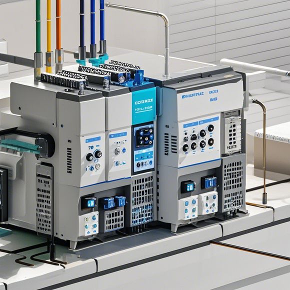
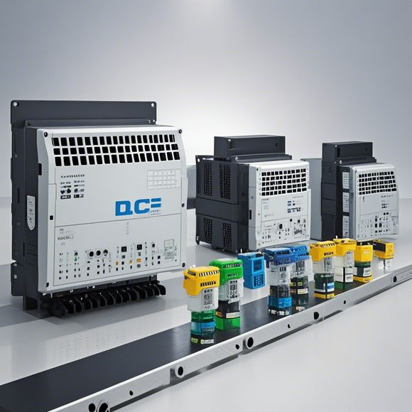
2、Understanding PLC Hardware - A detailed overview of the components used in an PLC system, including input/output modules, processor boards, and communication interfaces like Ethernet or Profinet.
3、PLC Software Development Kits - Explanations of the different software development kits available for PLCs. These are essential because they allow you to program your PLC with customized code that fits your specific needs.
4、Programming the PLC - Step-by-step instructions on how to write and compile your code using the programming language of your choice. This includes setting up a development environment and writing simple scripts to control basic functions.
5、Setting Up the PLC Environment - Detailed guidance on configuring the hardware components and connecting them together, ensuring everything is properly wired and set up for optimal performance.
6、Testing the PLC System - Explaining how to perform thorough tests before launching the system in production. This includes testing individual functions, interfacing with other systems, and monitoring outputs.
7、Handling Errors and Troubleshooting - Offering tips and techniques for troubleshooting common issues that may arise during the implementation process.
8、Advanced Features - Highlighting some of the more advanced features that PLCs offer, such as real-time data processing, complex algorithms, and customizable user interfaces.
9、Maintenance and Support - Explaining how to keep your PLC system running smoothly and how to seek help from the manufacturer or third-party support when necessary.
10、Future-proofing Your PLC System - Advice on how to plan for future upgrades and expansions to ensure that your PLC system remains relevant in the long term.
This guide is not just a collection of technical details; it's also designed to provide practical examples and case studies to illustrate how these concepts apply in real-world scenarios. By following this guide, you will be well-equipped to implement a robust and efficient PLC control system that meets the needs of your business or industry.
Let me know if you have any questions or need further assistance with the guide. I'm here to help!

Content expansion reading:
Content:
Hey there! If you're new to the world of PLCs (Programmable Logic Controllers), or you're looking to brush up on your knowledge, understanding PLC control system wiring diagrams is a crucial step. These diagrams are the blueprint that tells you how all the components of a PLC system are connected and how they work together. In this post, we're going to dive in and break down what you need to know to make sense of these diagrams.
First things first, let's talk about what a PLC actually does. A PLC is a type of industrial computer that's designed to control and automate various types of machinery and processes. It does this by reading input from sensors and switches, and then using that information to control outputs like motors, lights, and other devices.
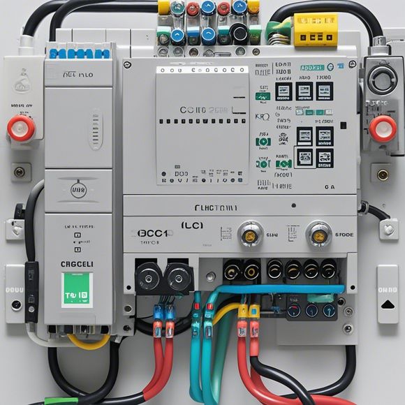
Now, let's get into the nitty-gritty of those wiring diagrams. A typical PLC control system wiring diagram will show you the following:
1、Power Supply: This is where the electrical power comes from to run the PLC and the devices it controls. You'll see the mains voltage, often 120 or 240 volts AC, and a transformer that steps down the voltage to a safer level for the PLC and its components.
2、PLC Unit: This is the heart of the system. It's where all the logic and decision-making happen. The diagram will show the PLC's input and output modules, as well as any communication ports.
3、Input Devices: These are the sensors, switches, and other devices that provide data to the PLC. They're usually connected to the PLC's input modules.
4、Output Devices: These are the devices that the PLC controls, like motors, valves, and lights. They're connected to the PLC's output modules.
5、Relay Logic: If the system has relay logic, the diagram will show how the relays are connected to the PLC and how they control higher power devices.
6、Control Panel: This is the user interface where you can monitor the system and make adjustments. It might include buttons, switches, and a display.
7、Emergency Stop: A crucial part of any industrial system, the emergency stop circuit will be clearly marked on the diagram. This is a safety feature that immediately stops all operations in case of an emergency.

8、Wiring Conduits: The diagram will show how the wires are run through conduits to connect all the components.
When you're looking at a PLC control system wiring diagram, it's important to pay attention to the symbols used. Each component has a specific symbol, and the wires are represented by lines with arrows that indicate the direction of the electrical flow.
Here's a quick rundown of some common symbols you'll see:
Input Devices: These might be represented by switches, sensors, or other symbols depending on the type of input.
Output Devices: These could be motors, lights, or other devices that require power to operate.
PLC: The PLC unit will have a specific symbol that reflects its function.
Relays: These are often shown as a coil and contacts.
Power Supply: The power supply symbol will indicate the voltage and amperage.
Remember, the key to understanding these diagrams is to take it step by step. Start by identifying the main components and then work your way through the connections. If you're ever unsure about a particular symbol or connection, don't hesitate to consult with a more experienced colleague or refer to the manufacturer's documentation.
Understanding PLC control system wiring diagrams is a fundamental skill for anyone working in industrial automation. It's not just about being able to read the diagrams; it's about being able to interpret them and troubleshoot issues when they arise. With a bit of practice and a good understanding of the principles behind PLCs, you'll be decoding these diagrams like a pro in no time.
Articles related to the knowledge points of this article:
PLC Controller Selection Guide for Foreign Trade Operations
PLC Controller for Manufacturing Automation
PLC Programming for Automation Control in the Manufacturing Industry
How to Use a PLC Controller for Your Business
Plumbers Rule! The Role of PLC Controllers in the World of Waterworks