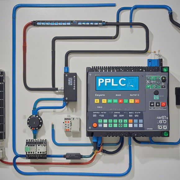
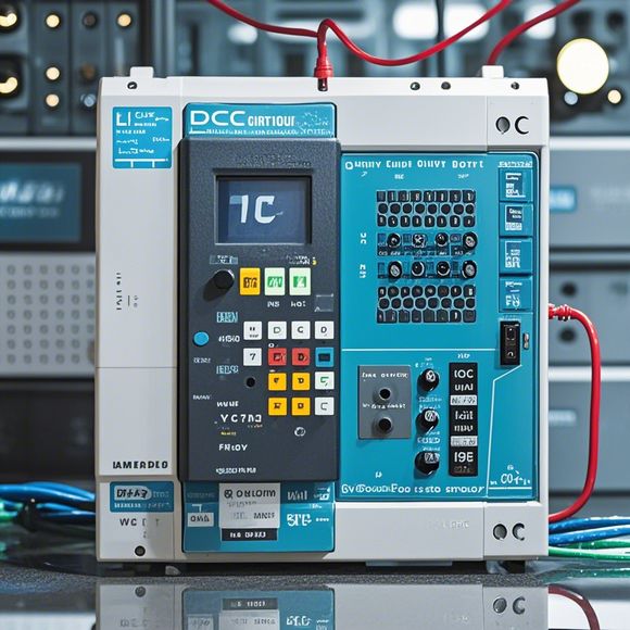
PLC Control System Overview
Sure, I'll provide a brief summary based on your content. PLC stands for Programmable Logic Controller, which is an industrial control system designed to automate and control industrial processes. It can handle a variety of tasks such as monitoring, controlling, and adjusting physical systems.In a PLC system, there are several key components:,1. The PLC itself, which acts as the central controller for the system.,2. Input devices, like sensors or switches that provide data about the environment.,3. Output devices, such as motors or lights that perform actions in response to the data from the input devices.,4. Programs, which define how the PLC should respond to inputs and outputs.The process of setting up a PLC system usually involves configuring the PLC with appropriate hardware and programming it with software. Afterward, the system can monitor and control various industrial processes, making it a valuable tool in manufacturing, automation, and other industries.
Introduction to PLC (Programmable Logic Controller) Systems
A programmable logic controller, or PLC, is a powerful tool in modern manufacturing and industrial automation. It stands for "programmable logic controller" and is designed to manage complex processes and systems by controlling various hardware devices such as motors, switches, sensors, and actuators. PLCs are widely used in industries like automotive, pharmaceuticals, and food processing, among others, because of their reliability, flexibility, and ease of programming. In this guide, we will explore the basic principles and applications of PLC systems.
The Importance of PLC Control Systems

Industrial automation relies heavily on PLC systems to ensure smooth production and high-quality output. By using these systems, manufacturers can optimize their operations, reduce waste, and improve efficiency. For example, in a manufacturing plant, PLCs can monitor and control the movement of conveyor belts, robotic arms, and other machinery, ensuring they operate efficiently and safely. They can also detect when machines need maintenance, alerting operators to prevent downtime.
The Basic Principles of PLCs
Before diving into specific applications, let's first understand the core principles behind PLCs. A PLC consists of an input/output interface, a microprocessor unit, and various memory modules. The microprocessor unit is the brain of the PLC, responsible for interpreting instructions from the input/output interface and performing calculations based on those instructions. This allows the PLC to respond to changes in the environment or commands from other systems.
The Input/Output Interface (I/O)
The input/output interface is what connects the PLC to external devices. It receives data from sensors, switches, and other input devices, and sends it to the PLC for processing. On the other hand, the output interface enables the PLC to communicate with other systems through motors, lights, and other devices. These devices can be directly controlled by the PLC or indirectly via a communication protocol like Ethernet.
The Microprocessor Unit
The microprocessor unit is the heart of the PLC. It interprets instructions from the I/O interface and performs calculations necessary to generate output signals for motors or other devices. The microprocessor unit can be programmed to perform various functions, including counting, sequencing, and monitoring.
Memory Modules
Memory modules store data and instructions for the microprocessor unit. These modules come in different sizes, with larger ones capable of storing more data or longer sequences of code. The memory modules are essential for running programs and storing variables that are needed for calculations and decisions made by the PLC.
Applications of PLC Systems
Now that we have a basic understanding of the principles behind PLCs, let's discuss some common applications of these systems.
Automation in Manufacturing
One of the most popular uses of PLCs in manufacturing is automation in assembly lines. With PLCs, machines can be controlled remotely, allowing for increased efficiency and reduced downtime. Additionally, PLCs can be used to monitor the performance of machines and identify any issues before they occur, ensuring high-quality products are produced consistently.
Process Control

In process control, PLCs are used to manage various industrial processes. For example, they can monitor temperature, pressure, flow rate, and other parameters in industrial plants. This data can then be used to optimize the operation of the system and prevent equipment failure.
Security and Safety
In today's world, safety is a top priority for many industries. PLCs can be used to implement advanced security systems, such as fire detection and alarms, smoke detectors, and emergency stop buttons. By monitoring these systems remotely, manufacturers can quickly respond to any potential hazards, minimizing risks and protecting employees.
Electrical Drives
In electrical drives, PLCs can be used to program motors to run at specific speeds or to control their direction. This allows for precise motion control, making it possible to maneuver heavy machinery with precision and accuracy.
Conclusion
In conclusion, PLCs are essential tools in modern industrial automation. They offer the ability to automate complex processes, monitor equipment performance, and ensure safety and security. By using PLC systems, manufacturers can optimize their operations, reduce waste, and produce high-quality products while minimizing downtime and costs. So next time you see a PLC system in action, take a moment to appreciate its role in modern industry.
Content expansion reading:
Content:
Hey there! If you're new to the world of PLCs (Programmable Logic Controllers), or you're looking to brush up on your knowledge, understanding PLC control system wiring diagrams is a crucial step. These diagrams are the blueprint that tells you how all the components of a PLC system are connected and how they work together. In this post, we're going to dive in and break down what you need to know to make sense of these diagrams.
First things first, let's talk about what a PLC actually does. A PLC is a type of industrial computer designed to control and automate various electromechanical processes. It's like the brain of a machine, receiving input from sensors and switches, processing that information according to pre-programmed instructions, and then outputting control signals to actuators and other devices.
Now, let's get into the nitty-gritty of those wiring diagrams. A typical PLC control system wiring diagram will show you the following:
1、Power Supply: This is the source of electrical power for the PLC. It's usually a 24-volt DC supply, but can also be AC depending on the system.
2、PLC Unit: This is the heart of the system. It's where all the logic and decision-making happen. The diagram will show the inputs and outputs (I/O) modules connected to the PLC.

3、Input Devices: These are the sensors, switches, and other devices that provide data to the PLC. They're represented by symbols on the diagram and are usually connected to the PLC's input modules.
4、Output Devices: These are the actuators, motors, and other devices that the PLC controls. They're connected to the PLC's output modules.
5、Relay Logic: If the system has relays, the diagram will show how they're connected to the PLC and other devices. Relays are like electrical switches that can control higher voltage or current devices.
6、Control Circuits: These are the wires and connections that allow the PLC to communicate with the input and output devices.
When you're looking at a PLC control system wiring diagram, it's important to pay attention to the following:
Terminal Numbers: Each terminal on the PLC and connected devices has a unique number. Make sure you understand how these numbers correspond to the actual physical terminals.
Signal Types: Different types of signals, like digital, analog, and serial, will be represented by specific symbols and wires on the diagram.
Power Distribution: How power is distributed from the main power supply to the various parts of the system.
Grounding: Proper grounding is essential for safety and to prevent electrical noise. Make sure the diagram shows proper ground connections.
Diagnostic Ports: These are used for programming and troubleshooting the PLC.
Remember, PLC control system wiring diagrams are not just static pictures; they're living documents that need to be updated as the system evolves. Regularly reviewing and updating these diagrams will help you keep track of changes and ensure that the system continues to operate efficiently and safely.
If you're new to PLCs, don't be intimidated by the complexity of these diagrams. They're just a tool to help you understand how everything fits together. With a bit of practice and some basic knowledge of electrical systems, you'll be reading and interpreting PLC control system wiring diagrams like a pro in no time.
Articles related to the knowledge points of this article:
PLC Controller Wiring Guideline
PLC Controller for Manufacturing Automation
How to Use a PLC Controller for Your Business
Plumbers Rule! The Role of PLC Controllers in the World of Waterworks