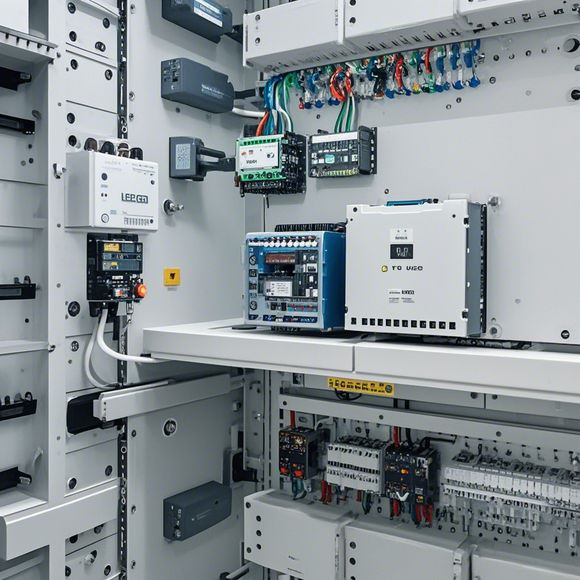
PLC Controller Wiring Diagram
Sure, I can generate a concise summary for the PLC (Programmable Logic Controller) wiring diagram in a structured manner. Here's an example of how it might look:---**Summary:**The PLC wiring diagram illustrates the electrical connections between various components inside the PLC system. The main components include the CPU (Central Processing Unit), input and output modules, sensors, actuators, switches, relays, and other control devices. Each component is connected to the PLC through wires that form circuitry paths.The schematic diagram shows the connections between these components, indicating the direction of current flow and the type of connection (e.g., direct current or alternating current). This helps engineers understand how to program the PLC software to control the various functions and processes within the system.The wiring diagram also includes information about the power requirements for each device and the potential voltage levels that need to be maintained during operation. This ensures the safety of the system and prevents damage due to overvoltage or undervoltage conditions.In summary, understanding the PLC wiring diagram is crucial for troubleshooting issues within the PLC system and ensuring optimal performance. It provides clear visual representation of the electrical connections between different components, allowing engineers to efficiently design and implement control systems using PLC technology.
As a forward-thinking and detail-oriented trader, it's crucial to ensure that your business operations run efficiently and securely. One critical aspect of ensuring this is having a clear understanding of the electrical wiring diagram for the PLC (Programmable Logic Controller) controller. In this guide, we will delve into the intricacies of the PLC controller wiring diagram and how it can help streamline operations and enhance productivity.

Firstly, let's start with the basics of the PLC controller. A Programmable Logic Controller is an electronic device that controls and monitors industrial processes. It operates by processing data received from sensors, switches, and other input devices, then directing control signals to output modules to manipulate the machinery or equipment in motion. The PLC controller is a crucial component in modern manufacturing and automation systems due to its ability to automate complex tasks with minimal human intervention, thereby enhancing safety, efficiency, and productivity.
Now, let's talk about the wiring diagram for the PLC controller. A wired diagram is a visual representation of the electrical connections between various components of the PLC controller. The purpose of the diagram is to provide a clear picture of how power is transmitted to and from the PLC, along with identifying the necessary inputs and outputs required for specific operations. This diagram is essential for troubleshooting, maintenance, and programming purposes, as it helps technicians identify the correct connections for various functions without having to physically inspect each circuit.
To understand the importance of the wiring diagram, consider the following example: suppose you have a production line where the PLC controller is responsible for controlling the speed of conveyor belts. The wiring diagram should clearly indicate the connection from the motor driver module to the PLC, and then to the motors themselves. This information is vital when determining if the motors are functioning correctly, and if there are any issues with the wiring or components. Without the wiring diagram, it would be challenging to pinpoint the exact source of the problem, leading to delays in fixing the issue and potentially causing further downtime.
Moreover, the wiring diagram also aids in programming. When programming the PLC, engineers rely heavily on the wiring diagram to determine the sequence of events that will occur during different phases of the process. By analyzing the diagram, they can accurately write code that will enable the PLC to execute the necessary actions based on sensor inputs or predefined conditions. For instance, if a certain sensor detects a fault condition, the programmer may need to modify the code to trigger a failsafe mechanism or initiate emergency procedures. The wiring diagram becomes a vital tool in ensuring that these sequences are executed correctly.

Another advantage of the wiring diagram is its ability to simplify maintenance and troubleshooting. With a well-maintained wiring diagram, technicians can quickly identify which components are working and which ones require attention. They can use the diagram as a reference to check for loose connections, damaged cables, or other issues that may be causing performance problems. Additionally, if a component fails, the wiring diagram can guide them in the proper direction to find and fix it without needing to dismantle entire panels or sections of the PLC.
In conclusion, having a clear wiring diagram for the PLC controller is not only essential for maintaining and upgrading the system but also plays a crucial role in ensuring efficient and safe operations. By understanding its purpose, benefits, and practical application, businesses can leverage its power to drive their productivity and competitive edge. Remember, investing in a reliable and up-to-date wiring diagram is a wise decision that will reap significant rewards in the long run.
Content expansion reading:
Articles related to the knowledge points of this article:
PLC Controller Wiring Guideline
PLC Programming for Automation Control in the Manufacturing Industry
How to Use a PLC Controller for Your Business
PLC (Programmable Logic Controller) Control System Basics
Effective Strategies for Handling PLC Control System Faults
PLC Controller Advantages: A Comprehensive Guide for Success in Global Trade