Understanding PLC (Programmable Logic Controller) Circuit Diagrams in a Nutshell
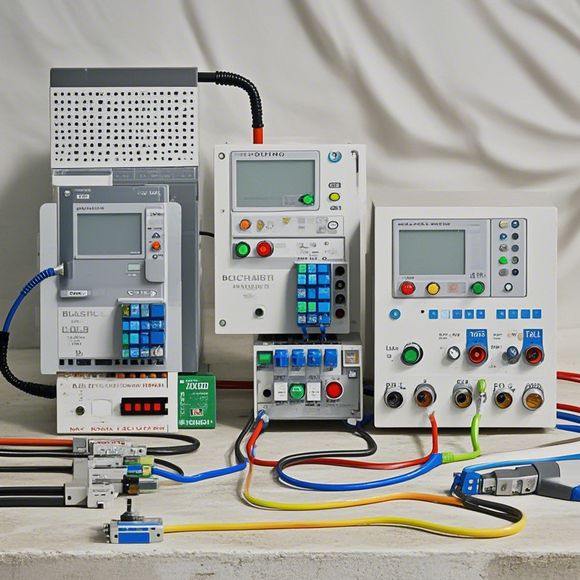
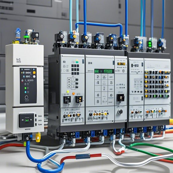
Sure, I can help you with understanding Programmable Logic Controller (PLC) circuit diagrams in a nutshell. A programmable logic controller (PLC) is an electronic device that is used to control the flow of industrial processes. It has circuit diagrams that represent the various components of the system, such as sensors, actuators, and control algorithms. These diagrams are essential for understanding how the PLC works and troubleshooting any issues that may arise.In a nutshell, the main components of a PLC circuit diagram include:1. Input Devices: These are devices that provide data from the process to the PLC. They can be sensors or other devices that measure parameters such as temperature, pressure, or flow rate.2. Output Devices: These are devices that provide feedback to the process. They can be actuators that control valves, pumps, or motors, or other devices that modify the process based on the input data.3. Control Algorithms: These are algorithms that determine how the PLC should respond to the input data. They can be simple logic functions or more complex algorithms that take into account multiple factors and make decisions based on them.Overall, understanding PLC circuit diagrams requires knowledge of the different components and their interactions. By studying these diagrams, engineers and technicians can quickly diagnose problems, optimize processes, and improve the performance of industrial systems.
Dear friends, today we have the pleasure of discussing the intricate world of PLC circuit diagrams. These diagrams are not just mere drawings, but rather they encapsulate an entire system's logic, communication pathways, and control functions. They serve as the backbone of industrial automation systems, enabling machines to operate with precision and efficiency. So let's dive into this fascinating world together, shall we?
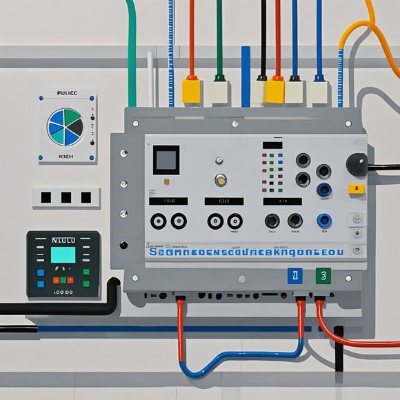
Firstly, let's break down what a PLC circuit diagram entails. It is essentially a visual representation of a computer-controlled process, showcasing how different components interact to perform specific functions. Each component is symbolized by its corresponding icon, and lines between them represent the flow of data and commands. The complexity of this diagram lies in the fact that it must be designed to be intuitive and easy to understand for those who work with it day-to-day. This is where the art of engineering comes into play.
Now, onto the nuts and bolts of understanding these diagrams. To start, familiarize yourself with the basic elements present in a PLC circuit diagram - sensors, actuators, processors, and output devices. Each one has a specific function, and their placement and connection determine the overall functionality of the system. For instance, a temperature sensor might be placed at a critical location to monitor the process's temperature, while an actuator could be used to adjust a valve's opening or closing based on the detected temperature.

As you study the diagram, pay special attention to the interconnectivity between components. Are there any loops or branches that can lead to unexpected outcomes? Are there any redundancies or overlapping functions that need to be minimized? A well-designed PLC circuit should be able to respond to changes in the environment without disrupting the overall operation of the system.
One common mistake many newcomers make is to assume that every part of the diagram needs to be connected to every other part. This isn't always the case, especially when considering safety protocols and environmental conditions. For instance, if a sensor detects a fault, it should send a signal to shut down the system rather than trying to communicate the error through a complex network of lines.
Another important aspect of understanding PLC circuit diagrams is the concept of redundancy. In some cases, it is necessary to have backup systems or redundant sensors to ensure continuous operation in the event of a failure. This is where the design principles of reliability and safety come into play. By carefully planning for these aspects, engineers can build systems that are not only efficient but also resilient to potential hazards.
Now, let's talk about the benefits that come with understanding these complex diagrams. Firstly, it empowers engineers to troubleshoot and diagnose issues quickly, reducing downtime and ensuring smooth operations. Secondly, it allows for better optimization and energy efficiency by minimizing unnecessary movements and processes. Lastly, it fosters collaboration among team members, as everyone has a clear idea of their roles and responsibilities in the system.
In conclusion, the world of PLC circuit diagrams may seem daunting at first glance, but with proper education and training, anyone can navigate this complex yet rewarding field. So next time you see a PLC circuit diagram in action, take a moment to appreciate the intricate dance of signals and actions that make it tick. Remember, every line represents a decision, and every decision shapes the future of your industry.
Content expansion reading:
Content:

Hey there, fellow tech enthusiasts! Today, we're diving into the world of Programmable Logic Controllers (PLCs) and how to make sense of those complex circuit diagrams that often come with them. Don't worry, even if you're new to the game, I'll break it down for you in a way that's easy to digest.
So, let's start with the basics. A PLC is essentially a brain for industrial electrical control systems. It's a ruggedized computer that's designed to withstand the harsh conditions of a manufacturing environment. The circuit diagram, on the other hand, is the blueprint that tells you how all the parts of the PLC are connected and how it communicates with other devices.
Now, when you first look at a PLC circuit diagram, it can be pretty intimidating with all those lines, symbols, and numbers. But fear not, once you understand the lingo, it's like learning a new language – suddenly, everything makes sense.
One of the first things you'll notice are the inputs and outputs. These are the connections between the PLC and the outside world. Inputs are like the eyes and ears of the PLC, they receive data from sensors, switches, or other devices. Outputs, on the other hand, are the hands and feet – they control actuators, motors, and other equipment.
The heart of the PLC is the processor, which is where all the magic happens. It's the part that takes the input data, runs it through the pre-programmed instructions, and decides what the outputs should be. This decision-making process is what controls the entire system.
Power supply is another key component. It's what keeps the PLC running, providing the necessary voltage and current to all the parts. Make sure you pay attention to the power ratings – you don't want to overload your PLC!
Now, let's talk about the logic. PLCs use a variety of logic gates and functions to process information. These can be represented by symbols on the circuit diagram. Understanding how these work is crucial to interpreting the diagram.

And let's not forget about the memory. PLCs have different types of memory for storing programs, data, and parameters. Knowing where to find specific information in the memory can be a game-changer when troubleshooting or making changes to the system.
Lastly, communication. PLCs don't work in isolation; they need to talk to other devices, like computers, HMIs, and other PLCs. The circuit diagram will show you the communication protocols and ports used for this exchange of data.
By breaking down the PLC circuit diagram into its constituent parts and understanding the role of each component, you'll be able to read and interpret these diagrams with ease. It's all about practice and knowing the vocabulary.
So there you have it, a quick and dirty guide to understanding PLC circuit diagrams. With a bit of time and patience, you'll be decoding these diagrams like a pro, and who knows, you might even start speaking the language of PLCs fluently!
Articles related to the knowledge points of this article:
PLC Controller for Manufacturing Automation
PLC Programming for Automation Control in the Manufacturing Industry
How to Use a PLC Controller for Your Business
Plumbers Rule! The Role of PLC Controllers in the World of Waterworks
Connecting a PLC Controller to Your Computer
PLC Controllers: A Comprehensive Guide to Understanding Their Prices