Mastering the Art of PLC Controller Wiring
Sure, here's a summary in口语化英语:,"So, the art of PLC controller wiring involves understanding how to connect various components together to create a functional system. It's important to follow the manufacturer's instructions and ensure that all wires are properly connected and labeled for easy maintenance."
In today's world, where technology is constantly evolving and improving, understanding how to properly wire a PLC (Programmable Logic Controller) controller can be crucial. As a外贸运营 in the field of industrial automation, having a deep knowledge of PLC wiring is not only essential but also beneficial. It helps in streamlining production processes, enhancing efficiency, and minimizing costs. In this guide, we will delve into the intricate world of PLC wiring, providing you with a comprehensive overview of the various components and their connections.

Firstly, let us understand what a PLC controller is. A PLC, or Programmable Logic Controller, is a device that allows for the automation of complex industrial systems by programming them to perform specific functions based on inputs from sensors, switches, and other control devices. The key feature that sets PLCs apart from traditional analogue controllers is the ability to store and recall program code, enabling them to respond to changing conditions in real-time.
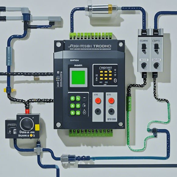
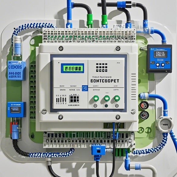
Now that we have a basic understanding of PLCs, let us talk about their connection. The first step in wiring a PLC is to connect it to the input and output devices that need to be controlled. This typically involves connecting a plc controller to various switches, sensors, motors, and other devices through cables. The choice of cable depends on the distance between the device and the PLC, as well as the type of electrical power required. For example, power cables are usually thick and conductive, while communication cables are thinner and may require shielding to prevent interference.
Once the cables are connected, the next step is to program the PLC using a software interface such as LabVIEW or RSLogix/Studio. This process involves writing specific code that defines the actions to be taken when different inputs are detected. The code can include logic statements, conditional statements, and loop structures, all of which determine the sequence and timing of operations.
The importance of programming cannot be overstated. Without a well-written code, a PLC controller may not function correctly, leading to downtime, lost production, and increased costs. Therefore, it is essential to spend adequate time developing and testing the code before finalizing the wiring.
Once programming is complete, the last step is to test the system thoroughly. This includes checking for proper connection between the PLC and its peripheral devices, verifying that all signals are transmitted and received correctly, and testing the entire system to ensure it operates as expected.
In conclusion, understanding how to wire a PLC controller requires a combination of technical knowledge and practical experience. With careful planning and attention to detail, you can create a robust and efficient system that meets your business needs. So, whether you're a seasoned expert or just starting out in this field, don't forget to invest time in learning how to wire a PLC controller. Your investment in this area will pay off in the long run, helping you stay ahead of the competition and achieve success in the industry.
Content expansion reading:

Content:
Hey there! If you're new to the world of PLCs (Programmable Logic Controllers), or you just need a refresher on how to read those complex wiring diagrams, you've come to the right place. PLCs are the brains of many industrial control systems, and being able to interpret their wiring diagrams is crucial for any electrical technician or engineer.
So, let's dive in and demystify those PLC controller wiring diagrams together. First things first, what exactly is a wiring diagram? It's a detailed visual representation of the physical connections between the various components of a PLC system. This includes the power supply, input devices, output devices, and the PLC itself.
When you're looking at a PLC wiring diagram, you'll typically see a mix of symbols and numbers. The symbols represent the different components, such as relays, switches, motors, and of course, the PLC. Each symbol has a specific meaning and is standardized across the industry to ensure consistency.
Now, let's talk about the different parts of a PLC controller wiring diagram. You'll usually see a power supply section, which is where the mains power enters the system. This is typically represented by a rectangle with "AC IN" or "DC IN" written inside. From there, the power is distributed to the various parts of the system.
Input devices are what tell the PLC what's going on in the real world. These can be switches, sensors, or any other device that provides data to the PLC. In the diagram, you'll see them represented by squares with numbers inside, indicating the channel number.
Output devices, on the other hand, are what the PLC controls. This could be anything from a motor to an alarm. They're usually represented by circles with numbers inside, just like the inputs.

The PLC itself is the heart of the system. It's where the logic is programmed, and it processes the input data to determine the output. The PLC symbol will often have multiple blocks inside, representing different parts of the controller.
To connect all these components, you'll see wires represented by lines in the diagram. Each wire will have a specific color and size, which is also standardized. The wire colors are important because they can indicate different types of signals or power.
When you're reading a PLC controller wiring diagram, it's also important to look for labels and notes. These can provide additional information about the function of each component or the wiring sequence.
Remember, practice makes perfect. The more wiring diagrams you look at and interpret, the better you'll become at understanding them. Always refer to the manufacturer's documentation for specific details about the PLC and its components.
And there you have it! A quick and easy guide to understanding PLC controller wiring diagrams. Whether you're working on a small control system or a large industrial setup, this knowledge will serve you well. Happy troubleshooting, and keep those diagrams handy!
Articles related to the knowledge points of this article:
PLC Controller for Manufacturing Automation
How to Use a PLC Controller for Your Business
Plumbers Rule! The Role of PLC Controllers in the World of Waterworks
The Role of Programmable Logic Controllers (PLCs) in Foreign Trade Operations
PLC Controllers: A Comprehensive Guide to Understanding Their Prices