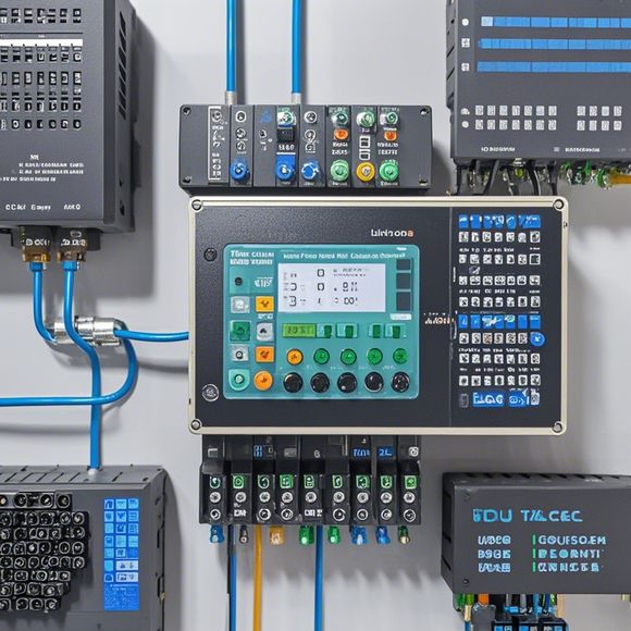
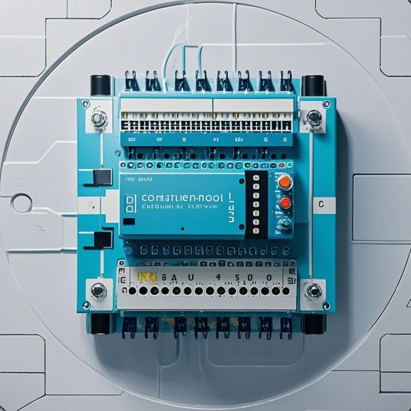
PLC Controller Wiring Diagram for Your Import and Export Business
Sure, I can generate a simplified English summary based on your content. However, since you haven't provided specific information about the details or context of your import and export business, I will create a generic summary:Your company is looking to streamline its operations by implementing a programmable logic controller (PLC) for its manufacturing processes. To facilitate this transition, we have created an electrical wiring diagram for your new PLC system. This diagram includes all the necessary components, such as sensors, actuators, switches, and other control modules, as well as their respective connections. We have also included detailed descriptions of each connection, ensuring that our team understands how to properly wire these components together for optimal performance. Additionally, we have included schematic diagrams to help visualize the overall layout and placement of the PLC within your factory environment. With this in place, we are confident that your company can take advantage of the advanced control capabilities offered by the PLC to improve productivity, reduce downtime, and increase safety standards throughout your manufacturing processes.
As an experienced foreign trade operator, understanding how to effectively use PLC (Programmable Logic Controller) controllers is critical. A well-maintained wiring diagram can help streamline operations, minimize errors, and increase efficiency. In this guide, we will provide you with a step-by-step guide to creating your PLC controller wiring diagram using English.
Step 1: Gather the Necessary Materials

Before you start, make sure you have all the necessary materials at hand. This includes a PLC controller, power supply, sensors, switches, and other electronic components. If you don't have any of these yet, consider purchasing them from reputable suppliers or manufacturers to ensure compatibility and longevity. Additionally, consider obtaining a basic wiring harness kit if you plan on connecting multiple components together.
Step 2: Determine the Connections
Identify the connections needed for each component in your system. This may require some experimentation and trial-and-error, so don't be afraid to make mistakes. Pay attention to the pin numbers and colors of different components, as they can vary depending on the brand or model of the PLC controller. Once you identify all the connections, mark the wires with markers or colored tape to avoid confusion.
Step 3: Draw the Wiring Diagram
Using a drawing software like AutoCAD, Microsoft Visio, or SolidWorks, create a wired diagram that accurately represents the connections between the PLC controller and its various components. Be sure to label each wire with its corresponding component number and pin number. Use clear lines and symbols to indicate the positive and negative connections, as well as any additional features such as relays, motors, or sensors.
Step 4: Test the System
Once you have finished drawing your wiring diagram, test it thoroughly. Connect each component to the appropriate pins, then turn on the power supply. Check that all connections are secure and that no short circuits occur. If there are any issues, adjust the diagram accordingly and try again. It may take several iterations to get everything working perfectly.
Step 5: Maintenance and Updates
Finally, keep your wiring diagram updated by regularly reviewing it for accuracy and maintaining the connections properly. Over time, new components and modifications can be added, so make sure to keep your wiring diagram up-to-date to ensure optimal performance throughout your import and export business.
In summary, creating an effective PLC controller wiring diagram is crucial for running a successful foreign trade operation. By following the steps outlined above, you can ensure that your system is connected securely and efficiently without any hassle. Remember to be patient, practice makes perfect, and always stay up-to-date with the latest advancements in automation technology.
Content expansion reading:
Content:

Hey there! If you're new to the world of PLCs (Programmable Logic Controllers), or you're just looking to brush up on your knowledge, understanding PLC controller wiring diagrams is a crucial step. These diagrams can seem intimidating at first, but once you know what to look for, they're actually pretty straightforward.
So, what exactly is a PLC controller wiring diagram? It's a visual representation of the electrical connections between the various components of a PLC system. This includes the power supply, the PLC itself, input devices (like sensors), output devices (like actuators), and any other peripherals.
The first thing you'll notice on a PLC wiring diagram is a set of symbols. Each symbol represents a different component or connection type. For example, you'll see symbols for the PLC, relays, timers, switches, and more. It's important to familiarize yourself with these symbols because they're the key to understanding the diagram.
Next, you'll see lines connecting these symbols. These lines represent the electrical paths between the components. They can indicate power lines, control signals, or data connections. Different colors are often used to denote different types of signals, so keep an eye out for that.
Power supply is a critical part of the diagram. You'll see the power source represented by a symbol, with lines branching out to the PLC and other components that need power. Make sure to note the voltage and amperage ratings to ensure you're not overloading the system.
Inputs and outputs are also clearly marked. Inputs are devices that provide data or signals to the PLC, like limit switches or temperature sensors. Outputs are devices that the PLC controls, such as motors or lights. The wiring diagram will show how these devices are connected to the PLC.
Now, let's talk about the PLC itself. The diagram will show the PLC's processor, memory, and I/O (input/output) modules. The I/O modules are where the inputs and outputs connect to the PLC. You'll see how the PLC communicates with these modules and how the modules connect to the other devices in the system.
When you're looking at a PLC controller wiring diagram, it's also important to consider the physical layout of the components. The diagram should reflect the actual placement of devices in the control panel or on the factory floor. This is crucial for both installation and troubleshooting.
If you're working with a complex system, the wiring diagram might include additional elements like junction boxes, terminal blocks, and safety devices. Each of these has a specific role to play in the overall operation of the system.
Remember, the key to understanding PLC controller wiring diagrams is to take it step by step. Start by identifying the symbols, then look at the connections, and finally, consider the physical layout. With a bit of practice, you'll be able to interpret these diagrams like a pro.
Articles related to the knowledge points of this article:
Mastering the Art of Plc Controllers: A Comprehensive Guide to Understand and Implement
How to Use a PLC Controller for Your Business
Connecting a PLC Controller to Your Computer
PLC Controllers: A Comprehensive Guide to Understanding Their Prices