PLC Control Cabinet Wiring Diagram
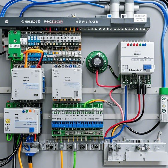
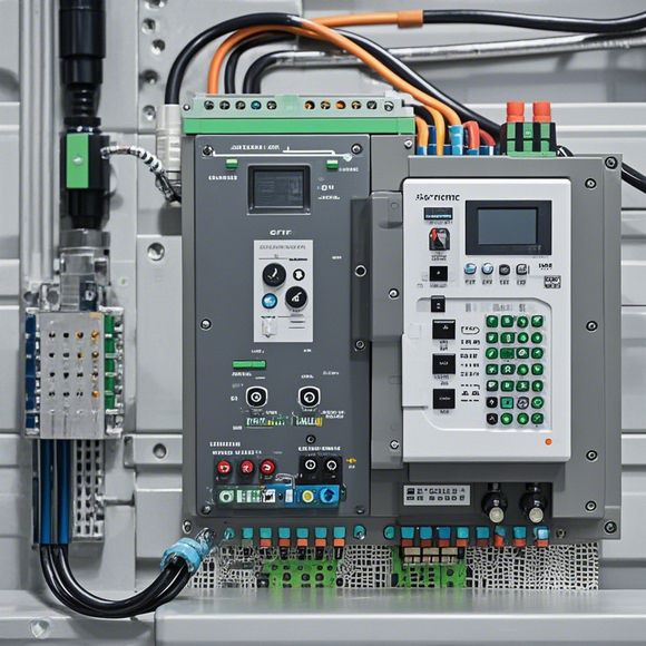
Certainly! Here's a brief summary in English for your PLC (Programmable Logic Controller) Control Cabinet Wiring Diagram:The diagram illustrates the wiring of a control cabinet that houses a programmable logic controller (PLC). It shows various components such as sensors, actuators, and switches connected to the PLC. The diagram also includes labels indicating which terminals are connected to which components. The schematic is organized in a way that helps understand how the different devices communicate with each other. Overall, it serves as an essential tool for troubleshooting and programming the PLC control system.
Introduction to PLC Control Cabinet Wiring Diagram:
In the world of industrial automation and control systems, the PLC (Programmable Logic Controller) plays a crucial role in ensuring smooth and efficient operations. A well-designed and implemented PLC control cabinet is the backbone of any production line, transforming raw materials into finished products with precision and reliability. The success of such a system hinges on its intricate wiring diagrams, which provide a clear map of all the components and connections within the cabinet. This guide will explore the various aspects of an PLC control cabinet's wiring diagram, highlighting its importance in achieving desired outcomes and minimizing errors.
1、Understanding the Basic Components
- The PLC itself acts as the brain of the control system, processing commands from sensors, actuators, and other devices based on predefined algorithms. It interfaces with various external hardware components, including motor drives, sensors, and communication networks.

- Sensors are critical for monitoring physical parameters such as temperature, pressure, or flow rate. They send data back to the PLC, allowing it to adjust settings accordingly.
- Actuators are devices that physically manipulate the environment, such as fans or pumps. They communicate with the PLC to trigger specific actions.
- Communication network connects the PLC to other devices and systems, enabling real-time data exchange and coordination of tasks across different areas of the facility.
2、Identifying the Connections
- Each component has its own set of wires that need to be properly connected to form a functional circuit. These connections must be made with care to ensure proper power distribution and signal transmission.
- Power supply wires deliver the necessary energy to each component, ensuring that they work correctly even during extended periods without human intervention.
- Grounding wires help to reduce electromagnetic interference and protect against potential electrical hazards.
- Data lines carry signals between different modules, allowing the PLC to process information effectively and make appropriate decisions.
3、Understanding the Signals
- Different types of signals are used to control various functions within the control system. For example, high-level signals like "Start" and "Stop" are commonly used to initiate and terminate processes, respectively.
- Lower-level signals such as "Ready" and "Acknowledged" indicate successful completion of a task or operation. They allow components to communicate with one another efficiently and prevent unnecessary wait states.
- Error signals serve as warning indicators for any issues within the control system, allowing operators to take corrective action before problems escalate.
4、Managing the Complexity
- As the number of components increases, so does the complexity of the wiring diagram. It becomes essential to have a clear understanding of how these components interact and how they contribute to achieving the desired outcome.
- By analyzing the connections, you can identify potential points of failure or inefficiencies and address them before they become more serious problems.
- Maintaining a consistent layout throughout the control cabinet helps streamline maintenance and troubleshooting efforts. This ensures that any changes made do not disrupt ongoing operations unnecessarily.
5、Enhancing Safety
- Properly designed wiring diagrams play a vital role in enhancing safety within the control system. They ensure that all components are connected securely and that there are no exposed wires or loose connections that could lead to accidental activation or damage.
- By implementing appropriate safety features such as overload protections and fault detection systems, you can significantly reduce the risk of fires, explosions, or other dangerous situations.
- Regular testing and inspections of the wiring diagrams can also help identify potential hazards before they cause harm to people or assets.
6、Compliance with Regulations
- Ensuring compliance with relevant regulations is crucial for any industrial setting, including PLC control cabinets. These regulations often require specific standards for electrical connections, grounding practices, and other aspects of installation.
- By adhering to these standards, you can avoid costly fines, legal penalties, or even product recalls caused by non-compliant wiring diagrams.
- Conducting regular audits of your installations can help identify any potential gaps in regulation enforcement and take proactive steps to ensure continued compliance.
7、Future-Proofing
- As technology advances, so too does the need for future-proofing in PLC control cabinet wiring diagrams. By incorporating features such as modularity and scalability, you can easily adapt your system to new applications or changing requirements.

- Modular design allows for easy integration of new components or software updates without requiring major rewiring. Scalability means that the same design can handle varying levels of complexity, making it ideal for expanding into new markets or increasing production capacity.
- By investing in reliable and innovative technologies, you can ensure that your PLC control cabinet remains at the forefront of automation innovation for years to come.
8、Maintenance and Upkeep
- Proper maintenance of the PLC control cabinet is essential for maintaining its performance and extending its lifespan. This includes routine inspections and adjustments to ensure that all components are functioning optimally.
- Regular cleaning and lubrication of moving parts can help minimize wear and tear, improving efficiency and reducing downtime.
- By adopting best practices for maintenance, you can minimize unexpected repairs or replacements, saving both time and money.
9、Cost-Effective Solutions
- When choosing a PLC control cabinet, it's important to consider cost-effective solutions that offer the necessary features without breaking the bank. Look for models with built-in diagnostics, remote access capabilities, and other advanced features that can save you money in the long run.
- By comparing prices and benefits across different vendors, you can find a solution that meets your specific needs while staying within your budget.
- Consider leasing or financing options if you need a larger investment upfront but want flexibility in terms of payment schedules and interest rates.
10、Conclusion
- In conclusion, the PLC control cabinet wiring diagram is a critical component of any modern industrial setup. Its ability to effectively communicate and coordinate with various components is essential for ensuring smooth operation and maximizing productivity. By carefully examining and following the guidelines outlined above, you can ensure that your PLC control cabinet is both reliable and cost-effective, ready to handle whatever challenges come your way. So why wait? Start today and bring your industrial automation goals closer to reality!
Content expansion reading:
Content:
Hey there! If you're new to the world of PLCs (Programmable Logic Controllers) and their control panels, or if you're just looking to brush up on your knowledge, you've come to the right place. Today, we're going to dive into the world of PLC control panel wiring diagrams. Don't worry, we're going to keep it simple and make it fun!
So, what exactly is a PLC control panel wiring diagram? It's like a blueprint for your control panel, showing you how all the wires connect to the different components inside. It's super important because it tells you where everything goes and how it all fits together. Without it, it'd be like trying to build a house without a plan!
Now, let's talk about the different parts of a PLC control panel wiring diagram. First up, you've got your power supply. This is like the heart of the system, providing the electricity that everything else needs to work. Then you've got your PLC itself, which is the brain, processing all the information and making decisions based on the program you've set up.
Around the PLC, you'll see inputs and outputs. Inputs are like the eyes and ears of the PLC, they receive data from sensors or switches, telling the PLC what's going on in the real world. Outputs, on the other hand, are like the hands and feet. They take the instructions from the PLC and make things happen, like turning on a motor or lighting up an indicator.
The wiring diagram will also show you how the PLC is connected to other devices, like motors, valves, and displays. These connections are like the nervous system, sending signals back and forth to make the whole system work.
When you're looking at a wiring diagram, it's important to pay attention to the symbols. Each component has its own symbol, and once you learn what they mean, you can read the diagram like a book. For example, a circle with a line through it is a switch, while a square with a plus sign is a relay.
One of the most important things to remember is that wiring diagrams are color-coded. Different colors represent different types of signals or power. For instance, red wires often carry high-voltage power, while blue wires might be used for control signals.
As you're working with PLC control panel wiring diagrams, it's also crucial to understand the concept of ladder logic. This is the programming language of PLCs, and it's what tells the PLC what to do when it receives certain inputs. Ladder logic is made up of rungs, which are like the steps in a recipe. Each rung has two sides, like a ladder, and the PLC follows these steps in order to control the outputs.
Remember, safety is paramount when working with PLC control panels. Always make sure the power is off before you start messing with the wiring, and never assume a wire is safe to touch just because it's not live right now. Always check with a multimeter before you start poking around.
Lastly, if you're ever stuck or confused by a wiring diagram, don't hesitate to ask for help. There are plenty of resources out there, from online forums to experienced colleagues, who can guide you through the complexities of PLC control panel wiring.
So there you have it, a quick and easy guide to understanding PLC control panel wiring diagrams. Whether you're a seasoned pro or just starting out, keeping these basics in mind will help you navigate the world of PLCs with confidence. Happy wiring!
Articles related to the knowledge points of this article:
The cost of a PLC Controller: A Comprehensive Analysis
How to Use a PLC Controller for Your Business
PLC (Programmable Logic Controller) Control System Basics
Connecting a PLC Controller to Your Computer
PLC Controllers: A Comprehensive Guide to Understanding Their Prices