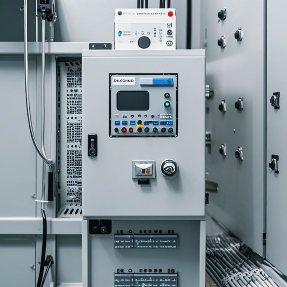
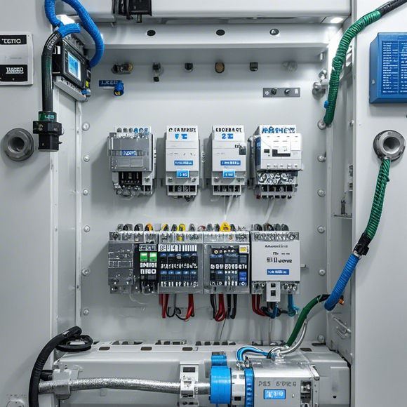
Introduction to PLC (Programmable Logic Controllers) Wire Harnessing and Connector Use
Certainly! Here's a brief introduction to Programmable Logic Controllers (PLCs) and their wire harnessing and connector usage:PLCs are electronic control systems that allow for the automation of industrial processes. They can be programmed to perform various tasks, such as controlling machines or monitoring sensor data. When connecting PLCs to other devices, it's important to use appropriate wire harnesses and connectors to ensure proper communication.Wire harnesses are bundles of wires designed to protect the wires during installation and provide a secure and organized way to route them from one point to another. They come in different sizes and configurations to accommodate various applications. Connectors are also used to connect PLCs to other equipment, ensuring that the wiring is secure and reliable.When choosing wire harnesses and connectors, it's important to consider factors such as the type of wires being used, the voltage and current capacity required, and the application's safety requirements. Properly selecting the right components ensures that the PLCs are connected securely and effectively, allowing for reliable operation.
In the world of modern industrial automation, programmable logic controllers (PLCs) play a vital role in controlling various systems. From simple factory automation processes to complex industrial environments, PLCs have become the go-to solution for managing complex tasks with precision and efficiency. When it comes to wiring and connecting the components of a PLC, proper knowledge and practice are essential for ensuring that the system operates smoothly and reliably. In this guide, we will delve into the details of PLC wire harnessing and its associated connectors to help you master this crucial aspect of PLC installation.
At the heart of any PLC system lies the wire harness, which serves as the backbone of the electrical connections between different components of the control system. A well-designed wire harness ensures that all components receive the appropriate power supply and communicate effectively without interference or errors. Therefore, understanding how to properly wire up an PLC system is crucial for maintaining its functionality and preventing potential issues.
When working on a wire harness, it is important to start by identifying the components that need to be connected to the PLC. This includes sensors, actuators, input/output modules, and other relevant devices. Once you have identified the components, you can proceed to plan the layout of the wire harness. The key principle here is to ensure that all wires are neatly organized while minimizing the number of connections required.

To achieve this, you may consider using specialized wire connectors such as screw terminals, push buttons, or plug-in connectors. These connectors allow for quick connection and disconnection of components, making it easier to troubleshoot any issues that arise during the installation process. Additionally, using wires with appropriate gauges and lengths is crucial for ensuring that they can safely carry the required current without overheating or shorting out.
One common mistake many newcomers to PLC installations make is not properly planning their wire harnesses. Without a clear layout, you run the risk of creating complex and confusing circuits that can lead to confusion and potential failures. Therefore, it is essential to carefully plan your wire layout before starting the installation process.
Once you have established the correct wire layout, it's time to begin connecting the wires. Here are some general tips to follow when wiring up your PLC:
1、Start by connecting the main power supply lines to the PLC. These should be routed through the appropriate conduits or trays to minimize potential damage during installation. It's also essential to ensure that the power supply lines are securely connected to the PLC and do not come into contact with any sensitive components.
2、Next, connect the sensors and actuators to the PLC's input/output ports. Make sure to match the correct pins from the sensors and actuators to the corresponding input/output ports on the PLC. You may need to use jumper wires or solder if necessary to secure the connections.
3、As you progress with the wiring, pay close attention to the placement of connectors and labels. Proper labeling helps identify each component and makes it easier to troubleshoot any issues in the future.
4、Finally, test the entire wire harness to ensure that all connections are secure and functional. Testing should involve checking for proper voltage levels and verifying that the connections are not damaged or broken. If you notice any issues during testing, address them immediately to prevent potential problems later.
In conclusion, PLC wire harnessing and connecting are critical aspects of PLC installation. By following proper guidelines and practices, you can avoid common mistakes and ensure that your system functions correctly and efficiently. Remember, patience and attention to detail are key when it comes to wire harnessing; take your time and ensure that each connection is secure before moving on to the next step. With these tips in mind, you can confidently tackle even the most challenging PLC installation projects.
Content expansion reading:

Content:
Hey there! If you're new to the world of PLCs (Programmable Logic Controllers), or you just need a refresher on how to read those complex wiring diagrams, you've come to the right place. PLCs are the brains of many industrial control systems, and being able to interpret their wiring diagrams is crucial for any electrical technician or engineer. Let's dive in and demystify those diagrams together!
First things first, what is a PLC controller wiring diagram? It's a blueprint that shows how all the electrical components of a PLC system are interconnected. This includes the power supply, input devices (like sensors), output devices (like motors or lights), and the PLC itself. Each component is represented by a specific symbol, and the lines between them indicate the flow of electricity or data.
Now, let's break down the basics of what you'll see in a typical PLC controller wiring diagram:
1、Power Supply: This is where the electrical power comes from to run the entire system. You'll see a symbol for the power source, often with a plus and minus sign to indicate the flow of current.
2、Input Devices: These are the sensors or switches that provide data to the PLC. They're represented by symbols that look like buttons, switches, or the specific type of sensor (like a photoelectric or proximity sensor).
3、Output Devices: These are the components that receive signals from the PLC to perform an action. They might be motors, lights, solenoids, or anything else that needs to be controlled. Output devices are usually represented by symbols that look like the device they represent.
4、PLC: The heart of the system, the PLC itself is represented by a rectangular block with various ports for inputs and outputs. It might also have additional ports for programming or communication.
5、Wiring: The lines between the symbols represent the wires that connect everything together. They can be solid lines for power and control signals, or dashed lines for pilot or control wiring.

6、Terminal Blocks: These are the connectors where wires are attached to the PLC and other devices. They're usually represented by a series of squares or rectangles with numbers indicating the terminal locations.
When you're looking at a PLC controller wiring diagram, it's important to pay attention to the following details:
Power Ratings: Make sure all components are rated for the correct voltage and current.
Wire Size and Type: Ensure that the wires are suitable for the power and control signals they carry.
Grounding: Proper grounding is essential for safety and to prevent electrical noise.
Diagnostic Points: These are points in the diagram where you can test the system to ensure it's functioning correctly.
Remember, practice makes perfect. The more wiring diagrams you study and the more you apply this knowledge in the field, the better you'll become at interpreting them. Always refer to the manufacturer's documentation for specific details and safety information. And if you're ever in doubt, consult with a more experienced colleague or refer to industry standards.
So there you have it, a quick rundown of PLC controller wiring diagrams. With a bit of time and effort, you'll be decoding these diagrams like a pro!
Articles related to the knowledge points of this article:
PLC Controller Selection Guide for Foreign Trade Operations
PLC Programming for Automation Control in the Manufacturing Industry
How to Use a PLC Controller for Your Business
PLC (Programmable Logic Controller) Control System Basics
Plumbers Rule! The Role of PLC Controllers in the World of Waterworks