PLC Controller Wiring Diagram Guide - An Interactive Tutorial for Businesses in the Supply Chain
In this interactive tutorial, we'll be covering the wiring diagram for PLC controllers in supply chain businesses. This guide will provide you with all the necessary information to understand the different components involved and how they interact to create a functional system.The first step is to familiarize yourself with the basics of PLC control systems, such as their functions, applications, and benefits. Once you have a good understanding of these concepts, we will delve into the specifics of the wiring diagram, including the various types of cables used, connectors, and terminal blocks.We will also explore common mistakes that can occur during the wiring process and offer solutions to prevent them. Finally, we will provide tips on how to troubleshoot and diagnose issues that may arise during the implementation phase.By the end of this tutorial, you will be well-equipped to handle any PLC control system needs within your supply chain business. So let's get started!
Dear [Name],
Welcome to our comprehensive guide on how to properly wire your PLC controller. As a business in the supply chain, it's crucial to understand the basics of electrical connections and how they can be effectively managed with an PLC system. Our detailed tutorial will walk you through each step, from understanding the components and their functions to connecting them correctly. By following this guide, you will ensure that your PLC controller is functioning efficiently, which ultimately boosts productivity and reduces downtime.
Step 1: Gather Your Components

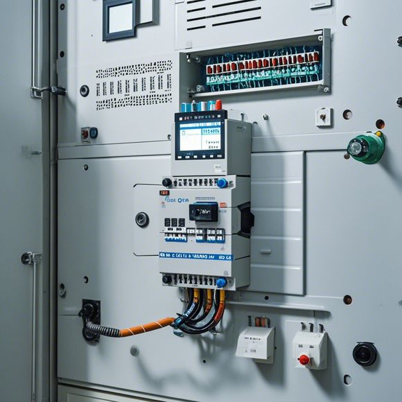
Before you start, gather all the necessary components such as the main power switch, sensors, actuators, and other devices connected to your PLC controller. This includes but is not limited to relay boards, input/output modules, and communication cables. Ensure that all components are of the same type and compatible with your PLC model for a smooth integration.
Step 2: Inspect the Wiring Diagram
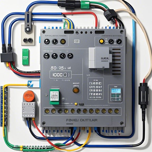
The first step towards ensuring successful wiring is by thoroughly examining the provided PLC controller wiring diagram. This diagram should detail the connections between various components, including the power source (power outlet or battery), sensors, actuators, and output devices. It also provides guidance on the appropriate terminals for each component to ensure proper connection.
Step 3: Disconnect All Power Sources
Before you connect any wires, disconnect all power sources from the PLC controller. This includes unplugging the power adapter or removing the battery from the device. This step is essential to prevent damage caused by improper connections during the wiring process.
Step 4: Connect the Main Power Switch
Connect the main power switch to the PLC controller. Make sure the switch is securely fastened and that there is no exposed wire. This is the control point that will initiate the flow of electricity to the controller.
Step 5: Assign Terminals to Each Component
Assign terminals to each component according to the wiring diagram. This involves connecting the positive and negative terminals of the wires to the corresponding terminals on the PLC controller. Be careful not to over-tighten screws, as this can cause damage or lead to loose connections.
Step 6: Connect the Sensors and Actuators
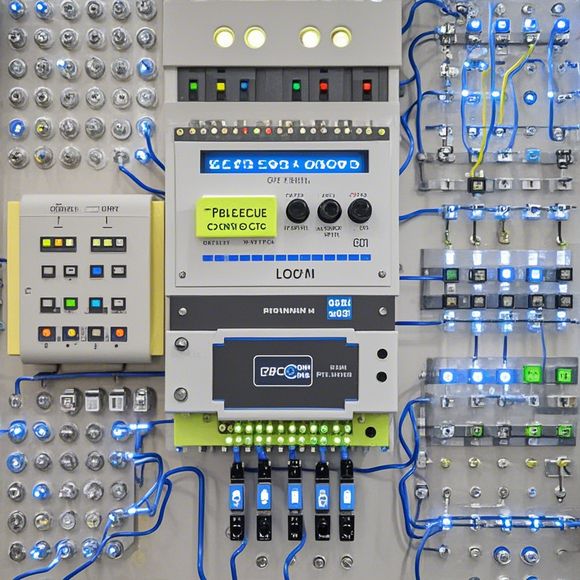
Next, connect the sensors and actuators to the PLC controller. Follow the wiring diagram carefully to ensure that the correct wires are connected to the respective terminals. For example, a temperature sensor might be wired to one of the input ports, while a motor could be wired to an output module.

Step 7: Test the System
After completing all connections, test your PLC controller to ensure that all components work together smoothly. Use a multimeter or a testing tool to verify that all connections are secure and that the circuitry is functioning correctly. If you notice any issues during testing, troubleshoot immediately to identify and fix the problem.
Step 8: Documentation and Maintenance
Finally, document all connections and configurations for future use and maintenance. Keep a record of all wiring details, including the type of wire used, resistance values, and any special requirements for your application. Regularly inspect the connections for wear and tear, and replace any damaged or worn-out components as needed.
In conclusion, properly wiring your PLC controller requires careful attention to detail. By following this guide, you can ensure a safe and reliable system that meets your business needs. Remember that proper maintenance and documentation are key to maintaining your PLC controller's performance over time. If you have any questions or concerns along the way, don't hesitate to reach out for assistance.
Content expansion reading:
Content:
Hey there! If you're new to the world of PLCs (Programmable Logic Controllers), or you're just looking to brush up on your knowledge, understanding PLC controller wiring diagrams is a crucial step. These diagrams can seem intimidating at first, but once you know what to look for, they're actually pretty straightforward.
So, let's dive in and break down what a PLC controller wiring diagram is and how to interpret it.
First things first, a PLC controller wiring diagram is a visual representation of the electrical connections between the various components of a PLC system. It shows you how the PLC is connected to input devices (like sensors), output devices (like motors or lights), and other peripheral equipment. The diagram is designed to help you understand the flow of electrical signals and how the system works as a whole.
When you're looking at a PLC controller wiring diagram, you'll typically see a few key elements:

1、PLC Module: This is the heart of the system. It's where the programming and logic take place.
2、Input Devices: These are the things that the PLC "reads" from the environment, like limit switches, temperature sensors, or push buttons.
3、Output Devices: These are the things that the PLC "controls," such as actuators, solenoids, or indicator lights.
4、Power Supplies: The PLC and the devices connected to it need power, so you'll see where the power is coming from and how it's distributed.
5、Wiring: The actual wires that connect all these components together.
Each component is usually represented by a specific symbol, and the wires are represented by lines with arrows that indicate the direction of the electrical signal. The wires are also color-coded to indicate their function, which can be really helpful when troubleshooting.
To read the diagram, start by identifying the PLC module and then follow the lines to see how it's connected to the input and output devices. Pay attention to the labels on the wires and the components to understand what each part of the system does.
It's also important to note that PLC controller wiring diagrams often include safety features, like emergency stop buttons or overload protection. These are designed to prevent accidents and damage to the equipment.
If you're working with a PLC controller wiring diagram for the first time, don't be afraid to ask questions. Whether it's your supervisor, a colleague, or an experienced technician, they can provide valuable insights and help you understand the intricacies of the system.
Remember, practice makes perfect. The more wiring diagrams you look at and the more you understand about how PLC systems work, the easier it will become to interpret these diagrams. So keep at it, and soon you'll be a pro at deciphering PLC controller wiring diagrams!
Articles related to the knowledge points of this article:
Plumbers Rule! The Role of PLC Controllers in the World of Waterworks
The Role of Programmable Logic Controllers (PLCs) in Foreign Trade Operations
Connecting a PLC Controller to Your Computer
PLC Controllers: A Comprehensive Guide to Understanding Their Prices